Imaging lens and imaging apparatus

a technology of imaging apparatus and lens, applied in the field of imaging lens and imaging apparatus, can solve the problems of increasing the cost of the lens system, and achieve the effects of low cost, long back focus, and small siz

Active Publication Date: 2014-03-11
TIANJIN OFILM OPTO ELECTRONICS CO LTD
View PDF23 Cites 5 Cited by
  • Summary
  • Abstract
  • Description
  • Claims
  • Application Information

AI Technical Summary

Benefits of technology

[0006]Meanwhile, in recent years, a lens system is generally used together with an imaging device, such as a CCD. Therefore, it is desirable that a back focus is long so that various filters can be arranged between the lens system and the imaging device, and that the lens system has high telecentricity so that an angle of incidence of peripheral rays entering the imaging device is small. While satisfying such requirements, a lens system that realizes small size, low cost, high performance and a small F-number similar to or more than those of conventional lens systems is demanded.
[0007]In lens systems disclosed in Patent Document 1, U.S. Patent Application Publication No. 20100103537 (Patent Document 3), U.S. Pat. No. 6,940,662 (Patent Document 4), Japanese Unexamined Patent Publication No. 2000-066091 (Patent Document 5), and Japanese Unexamined Patent Publication No. 10(1998)-213742 (Patent Document 6), all the lenses of each lens system are spherical lenses. Therefore, if glass is used as the material of the lenses, it is possible to produce lenses having excellent weather-resistance characteristics at low cost. However, if an aspherical surface is adopted, an improvement in the performance of the lens system would be expectable. The lens system disclosed in Patent Document 2 has F-number of 2.8, which is large, or a small F-number. In the lens system having the small F-number, a most-object-side lens is a plastic lens. Therefore, when the lens system is used in an in-vehicle camera or a surveillance camera, a protection means, such as a cover glass, is needed, and that increases the cost of the lens system.
[0008]In view of the foregoing circumstances, it is an object of the present invention to provide an imaging lens that is small-sized and structurable at low cost, and that has high telecentricity, long back focus and a small F-number, and that can achieve high optical performance. Further, it is another object of the present invention to provide an imaging apparatus including the imaging lens.

Problems solved by technology

Therefore, when the lens system is used in an in-vehicle camera or a surveillance camera, a protection means, such as a cover glass, is needed, and that increases the cost of the lens system.

Method used


Image

  • Imaging lens and imaging apparatus
  • Imaging lens and imaging apparatus
  • Imaging lens and imaging apparatus

Examples


Embodiment Construction

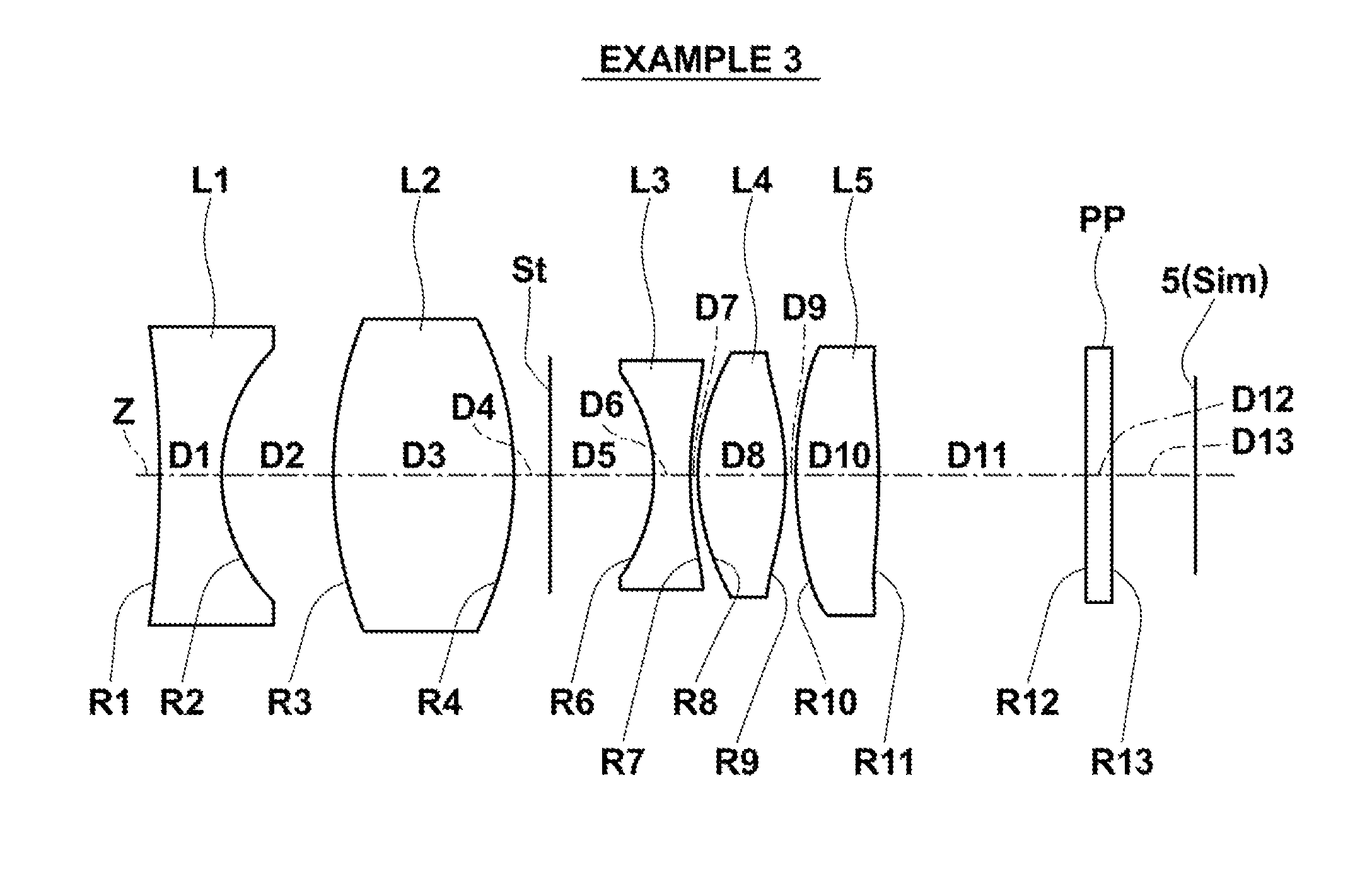
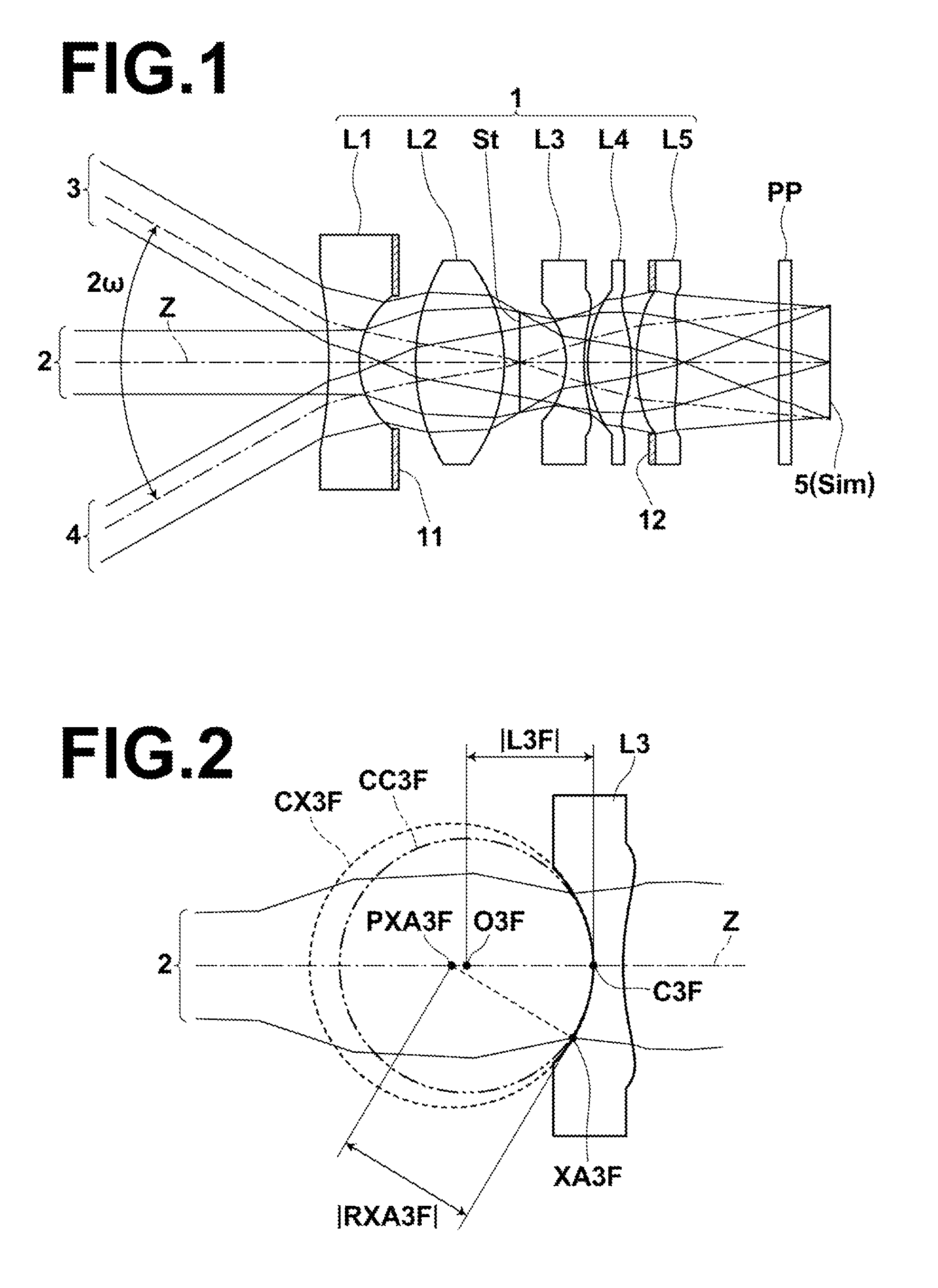
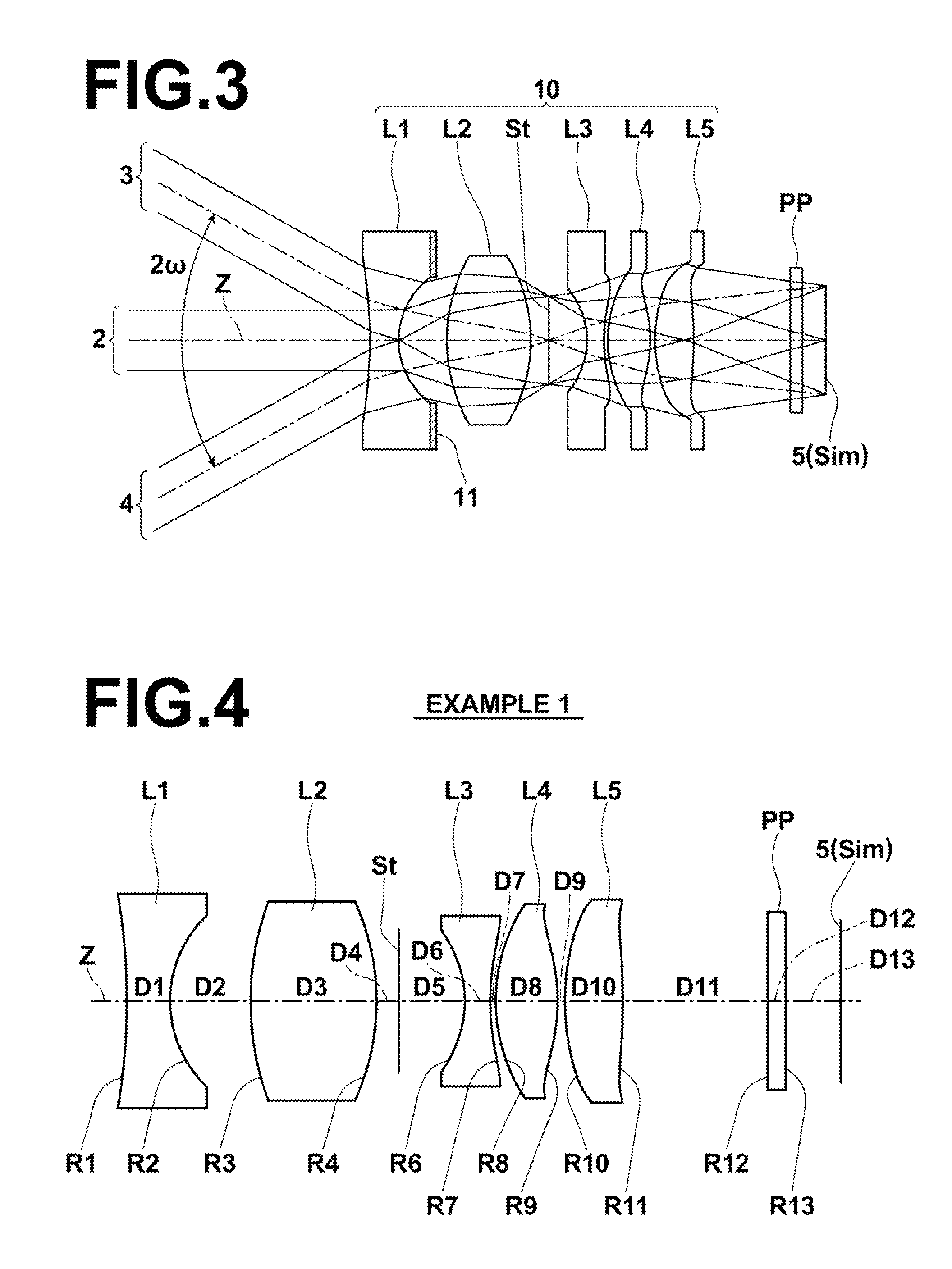
[0097]Hereinafter, embodiments of the present invention will be described with reference to drawings. First, an imaging lens according to an embodiment of the present invention will be described with reference to FIG. 1. FIG. 1 is a lens cross section of an imaging lens 1 according to an embodiment of the present invention. Further, FIG. 1 illustrates axial rays 2 from an object point at infinity, and off-axial rays 3, 4 at full angle of view 2. A structure example illustrated in FIG. 1 corresponds to an imaging lens in Example 1, which will be described later. In FIG. 1, the left side is the object side and the right side is the image side.

[0098]In FIG. 1, a case of applying the imaging lens 1 to an imaging apparatus is considered, and an imaging device 5 arranged at image plane Sim of the imaging lens 1 is also illustrated. In FIG. 1, the imaging device is illustrated in a simplified manner. However, in actual cases, the imaging device 5 is arranged in such a manner that the imagi...


PUM


Abstract

An imaging lens consists of a negative first lens having a concave object-side surface, a positive second lens, a negative third lens, a positive fourth lens having a convex object-side surface, and a positive fifth lens, which are in this order from an object side. A stop is arranged between an image-side surface of the first lens and an object-side surface of the third lens. When the focal length of an entire system is f, and the focal length of the first lens is f1, and the focal length of the second lens is f2, the following formula is satisfied:−1.30<f1 / f2>−0.65  (7).

Description

BACKGROUND OF THE INVENTION[0001]1. Field of the Invention[0002]The present invention relates to an imaging lens and an imaging apparatus. In particular, the present invention relates to an imaging lens appropriate for use in an in-vehicle camera, a camera for a mobile terminal, a surveillance camera, or the like using an imaging device, such as a CCD (Charge Coupled Device) and a CMOS (Complementary Metal Oxide Semiconductor). Further, the present invention relates to an imaging apparatus including the imaging lens.[0003]2. Description of the Related Art[0004]In recent years, the size of an imaging device, such as a CCD and a CMOS, became very small, and the resolution of the imaging device became very high. Consequently, the size of the body of imaging equipment including such an imaging device was reduced. Therefore, reduction in the size of an imaging lens mounted on the imaging equipment is also needed in addition to achievement of high optical performance. Meanwhile, lenses mo...

Claims


Application Information

Patent Timeline
Patent Type & Authority Patents(United States)
IPC IPC(8): G02B9/60
CPCG02B9/60G02B13/04G02B13/0045G02B13/22
Inventor ASAMI, TARO
Owner TIANJIN OFILM OPTO ELECTRONICS CO LTD
Why Eureka
Try Eureka