

Microphone assembly with integrated self-test circuitry
a microphone and circuit technology, applied in the direction of transducer details, electrostatic transducer microphones, electrical transducers, etc., can solve the problems of difficult testing of sensitive analog circuits, such as low-noise miniature microphone preamplifiers
- Summary
- Abstract
- Description
- Claims
- Application Information
AI Technical Summary
Benefits of technology
Problems solved by technology
Method used
Image

Examples
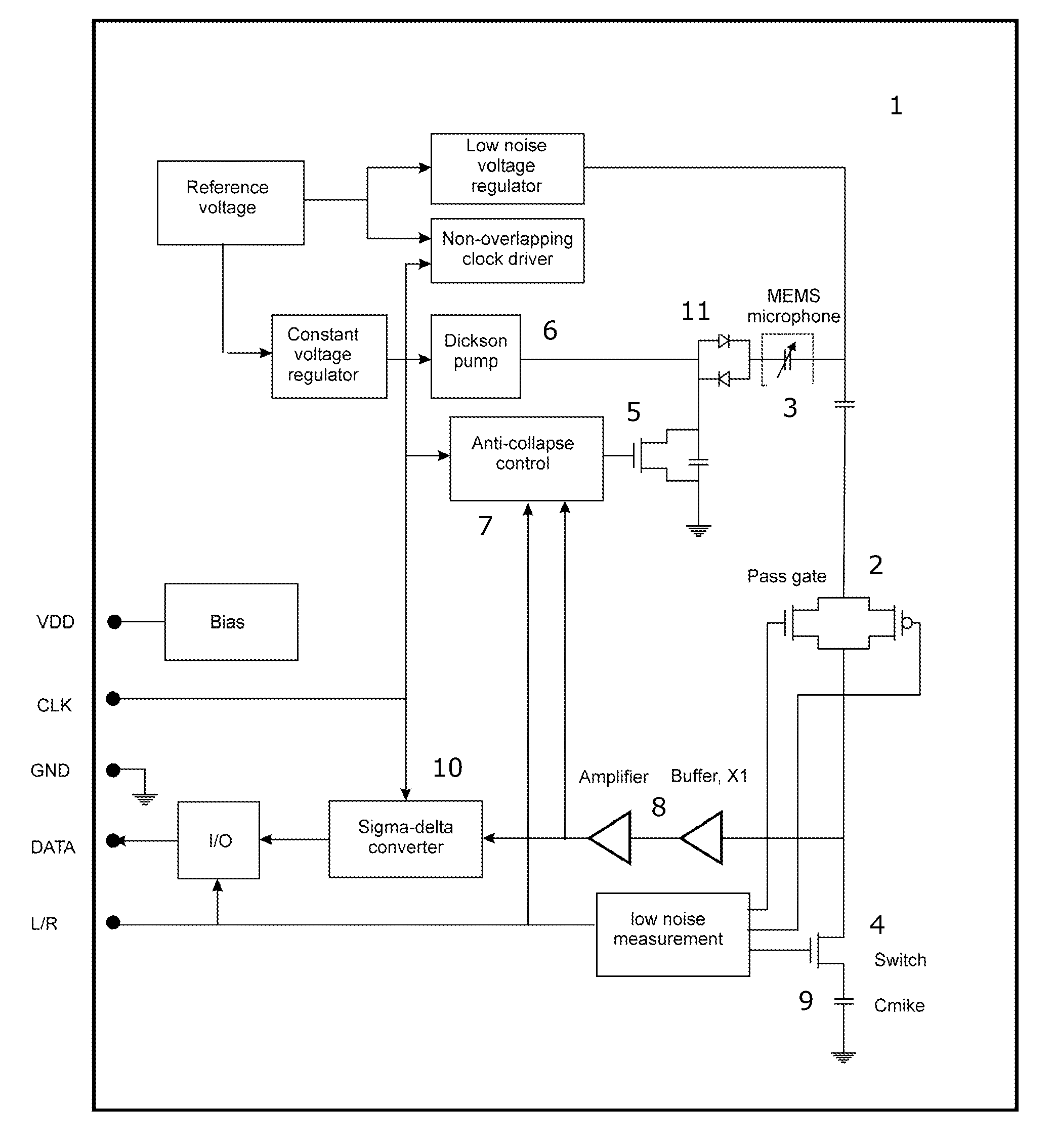
first embodiment
[0024]FIG. 1 shows a miniature microphone assembly according to the present invention;
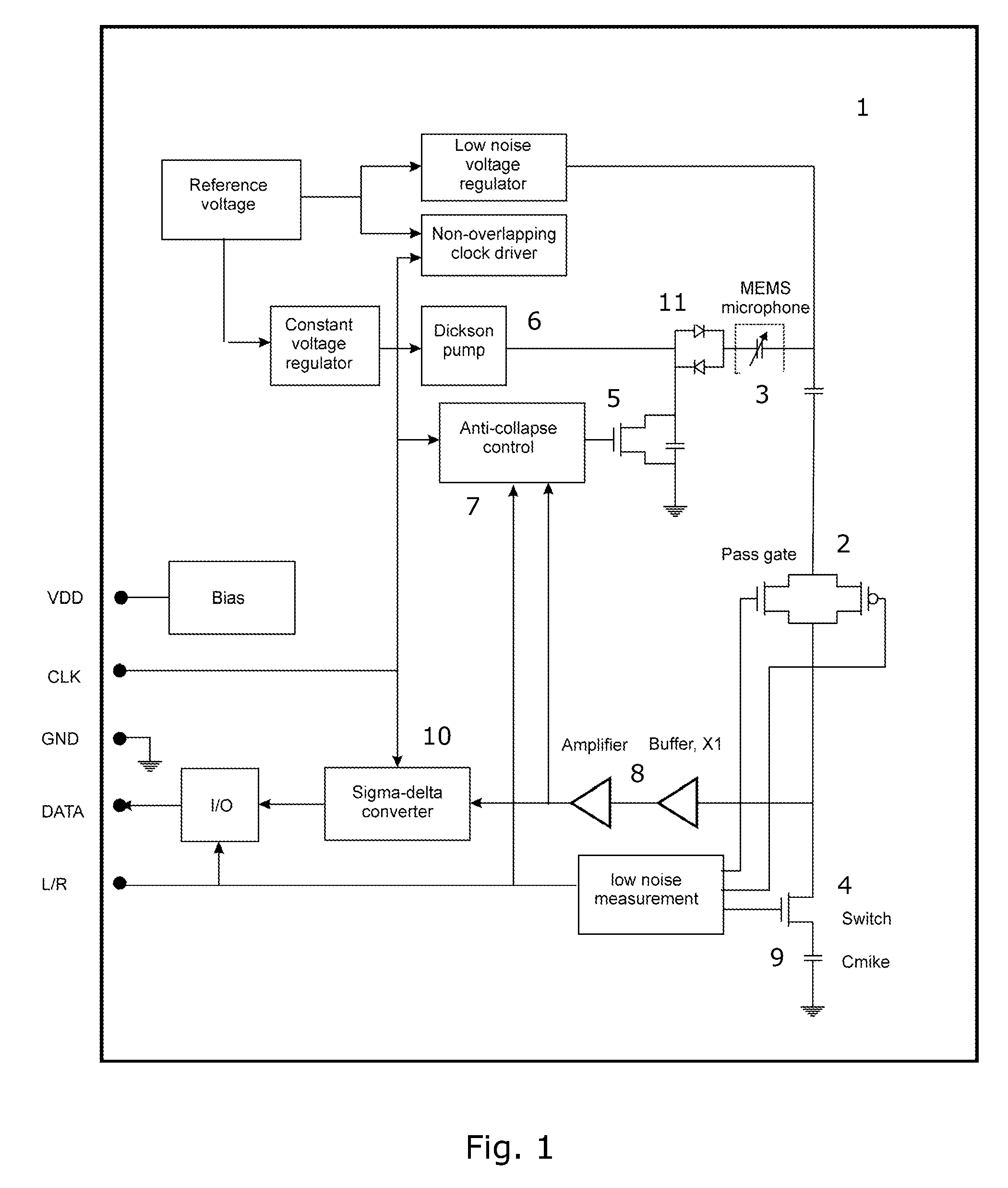
second embodiment
[0025]FIG. 2 shows a miniature microphone assembly according to the present invention; and
third embodiment
[0026]FIG. 3 shows a miniature microphone assembly according to the present invention.
[0027]While the invention is susceptible to various modifications and alternative forms, specific embodiments have been shown by way of example in the drawings and will be described in detail herein. It should be understood, however, that the invention is not intended to be limited to the particular forms disclosed. Rather, the invention is to cover all modifications, equivalents, and alternatives falling within the spirit and scope of the invention as defined by the appended claims.
PUM
 Abstract
Description
Claims
Application Information