Laser system and processing conditions for manufacturing bioabsorbable stents

a bioabsorbable stent and laser system technology, applied in the direction of manufacturing tools, prostheses, blood vessels, etc., can solve the problems of adverse effects of properties on the proper functioning of the device being manufactured

Inactive Publication Date: 2014-03-25
ABBOTT CARDIOVASCULAR
View PDF39 Cites 11 Cited by
  • Summary
  • Abstract
  • Description
  • Claims
  • Application Information

AI Technical Summary

Problems solved by technology

In general, the changes in properties are adverse to the proper functioning of a device that is being manufactured.

Method used


Image

  • Laser system and processing conditions for manufacturing bioabsorbable stents
  • Laser system and processing conditions for manufacturing bioabsorbable stents
  • Laser system and processing conditions for manufacturing bioabsorbable stents

Examples


examples

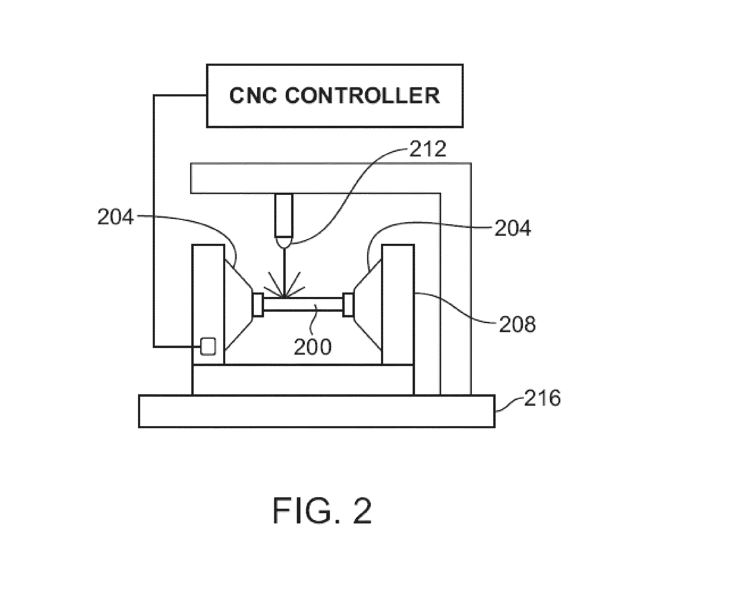
[0073]The examples and experimental data set forth below are for illustrative purposes only and are in no way meant to limit the invention. The following examples are given to aid in understanding the invention, but it is to be understood that the invention is not limited to the particular materials or procedures of examples.

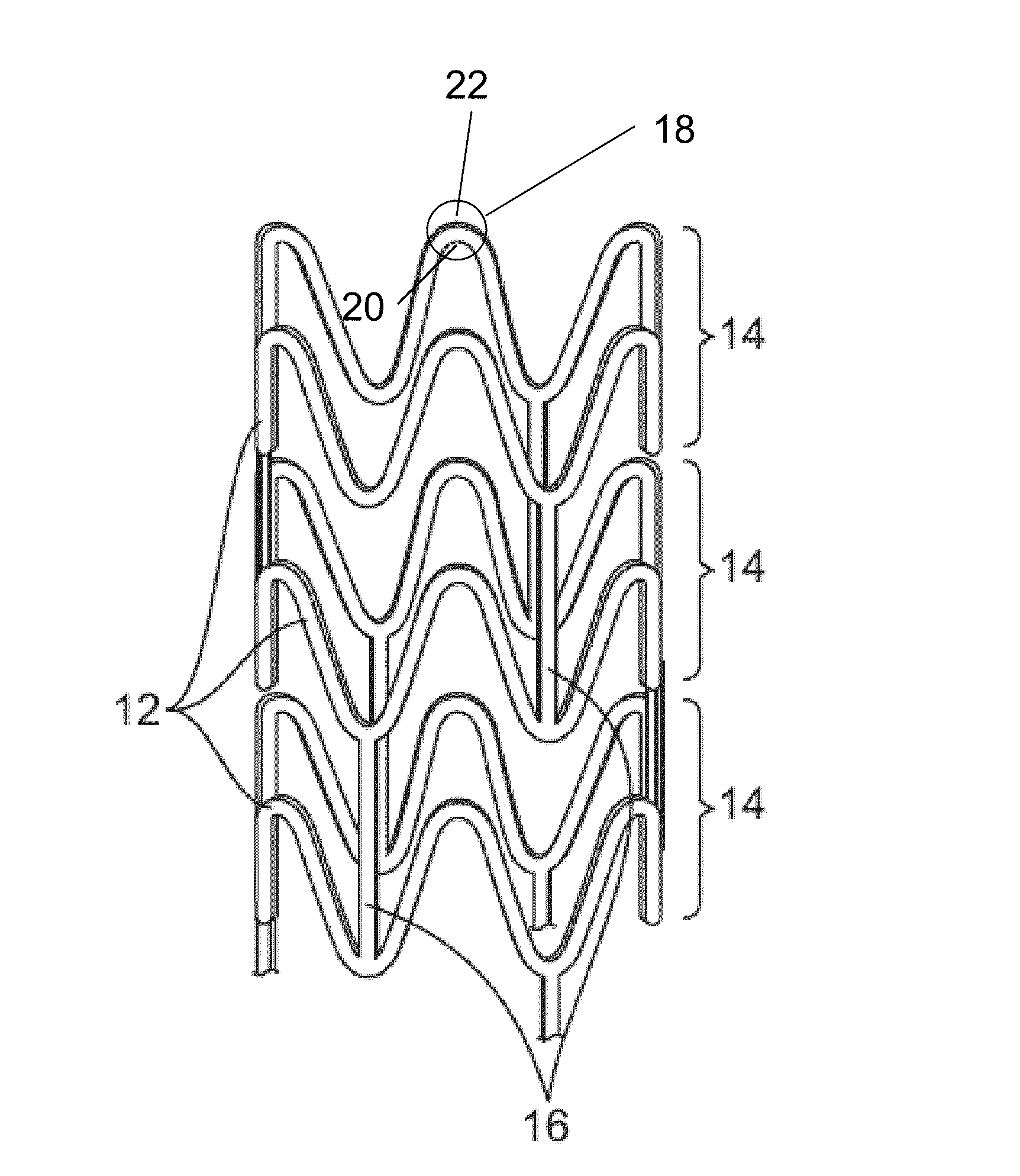
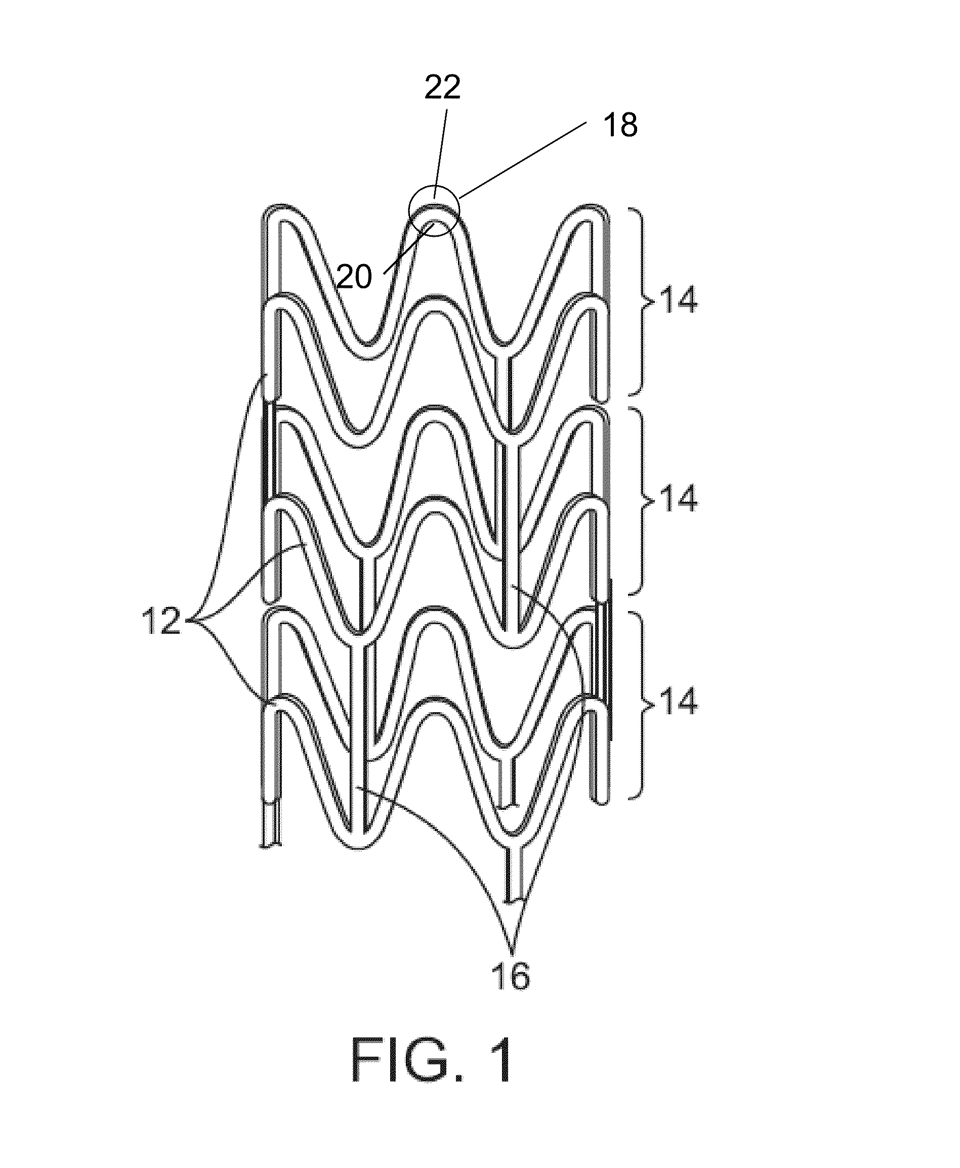
[0074]The following set of examples describes results of laser machining stents from PLLA tubing for seven different parameter combinations of pulse width and wavelength. The PLLA tubing was formed from an extrusion process from 100% PLLA resin. The dimensions of the tubing, the extruded dimensions, are: outside diameter (OD)=0.0066 inch and inside diameter (ID)=0.0025 inch. The extruded PLLA tubes were radially expanded according to a process described previously, for example, in U.S. application Ser. No. 12 / 554,589, which is incorporated by reference herein. The target percent radial expansion (% RE) was 400%, where % RE is deformed as 100%×(Inside Diameter of...


PUM

PropertyMeasurementUnit
wavelengthaaaaaaaaaa
thicknessaaaaaaaaaa
thicknessaaaaaaaaaa

Abstract

The present invention involves laser machining polymer substrates to form a stent with laser parameters that minimize damage to the substrate in a surface region adjacent to the machined edge surface. The wavelength and pulse width are selected for this unique application and they can be controlled to minimize the surface modifications (such as voids, cracks which are induced by the laser-material interaction) which contribute to the variation in mechanical properties with distance from the edge surface, bulk mechanical properties, or a combination thereof.

Description

BACKGROUND OF THE INVENTION[0001]1. Field of the Invention[0002]This invention relates to laser machining tubing to form stents.[0003]2. Description of the State of the Art[0004]This invention relates to laser machining of devices such as stents. Laser machining refers to removal of material accomplished through laser and target material interactions. Generally speaking, these processes include laser drilling, laser cutting, and laser grooving, marking or scribing. Laser machining processes transport photon energy into a target material in the form of thermal energy or photochemical energy. Material is removed by melting and blow away, or by direct vaporization / ablation.[0005]When a substrate is laser machined energy is transferred into the substrate. As a result, a region beyond the cutting edge is modified by the energy, which affect the properties in this region. In general, the changes in properties are adverse to the proper functioning of a device that is being manufactured. Th...

Claims


Application Information

Patent Timeline
Patent Type & Authority Patents(United States)
IPC IPC(8): B29C35/08
CPCB23K26/0635B23K26/4065A61F2/91A61F2/90B23K26/50B23K26/702B23K26/703B23K26/402A61F2240/001B23K26/0624B23K2103/42B23K2103/50A61F2/915
Inventor HARRINGTON, JOELVAUGHAN, RYANJOW, KEVINPIPPEY, WILLIAMCHEN, YUNG-MING
Owner ABBOTT CARDIOVASCULAR
Why Eureka
Try Eureka