Armature core, motor using same, and axial gap electrical rotating machine using same
- Summary
- Abstract
- Description
- Claims
- Application Information
AI Technical Summary
Benefits of technology
Problems solved by technology
Method used
Image

Examples
first embodiment
[0077]An embodiment in accordance with the invention will be described below, referring to FIGS. 1A to 6.
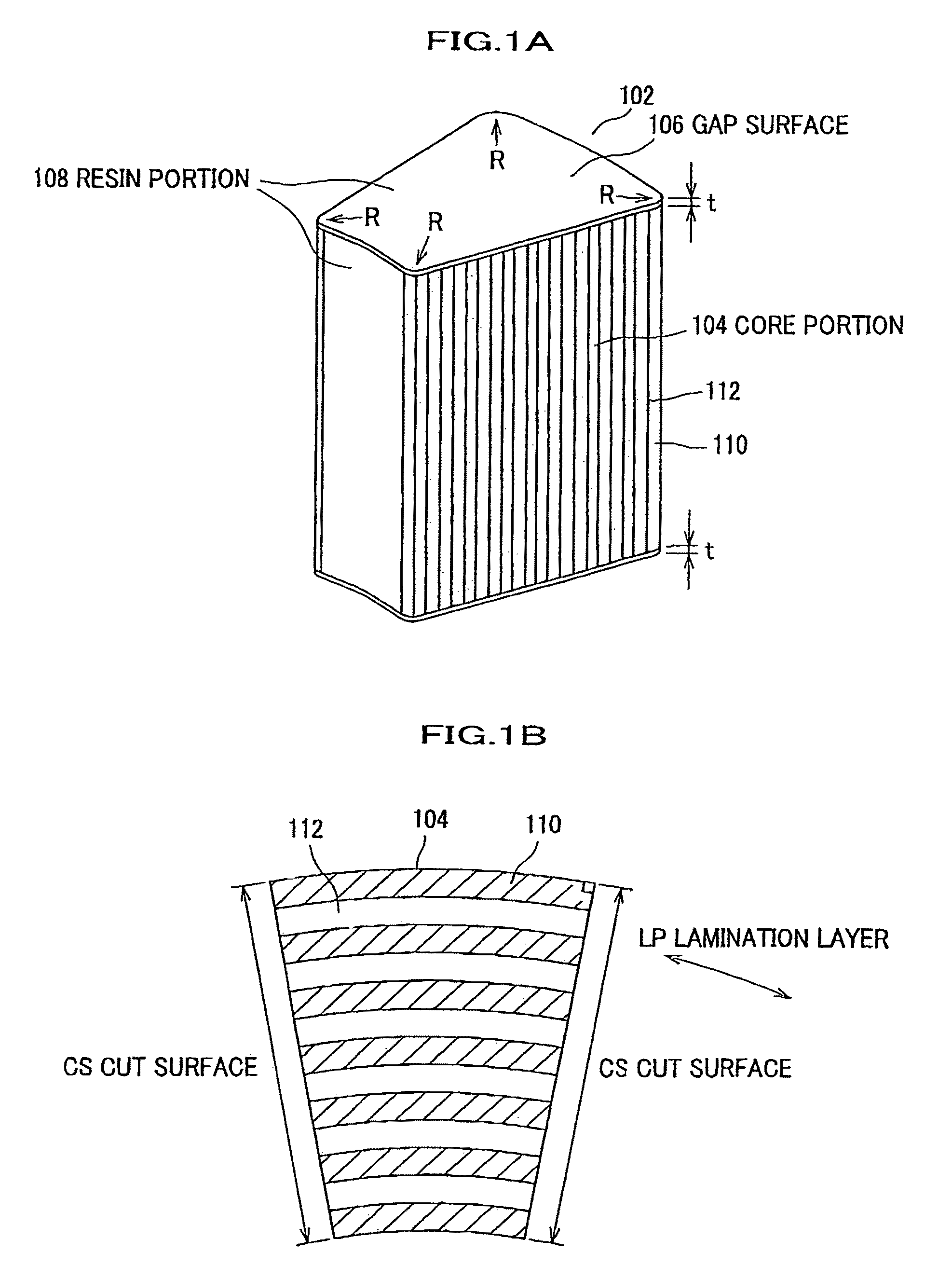
[0078]FIG. 1A shows an entire view of an amorphous core 102 in a first embodiment in accordance with the invention.
[0079]A core portion 104 of the amorphous core 102 is formed using amorphous metal (non-crystalline metal) elements 110 in a ribbon form (foil band) as an iron base to be in a laminated structure with sandwiched insulation resin material elements (hereinafter, referred to as resin) 112, wherein the amorphous metal elements 110 in the ribbon form are respectively bonded by the resin.
[0080]The core portion 104 is in a fan shape when viewed from the top or bottom.
[0081]Gap surfaces 106 at the top and bottom of the core portion 104 are provided with respective resin portions 108 being layers with an extremely thin thickness of mm so that the gap surfaces 106 are prevented from rusting. Further, the faces at the root side and the outer side of the fan shape of the core po...
second embodiment
[0093]FIG. 6 shows an axial gap motor using the amorphous cores 102 in the first embodiment. The motor using amorphous cores in the present embodiment includes a stator 304 having a plurality of amorphous cores 102 for the stator and winding wires 160 for the stator, and rotors 302, 304 having ferrite magnets 310 in a substantially rhombic shape. The two rotors 302, 304 have a structure sandwiching the stator 304 therebetween, and the motor in the present embodiment has nine poles of the stator and six poles of magnets. However, the number of the poles of the armature and the number of poles of magnets can have a combination other than this. Further, depending on the case, it is possible to set the rotors in the present embodiment on a fixing side, and make the stator rotatable.
[0094]FIG. 7 shows the detailed Shapes of the ferrite magnets 310, amorphous cores 102, and winding wire 160. FIG. 7 shows the shape of the motor, in FIG. 6, viewed from the top side. In order to reduce the c...
third embodiment
Modification of Third Embodiment
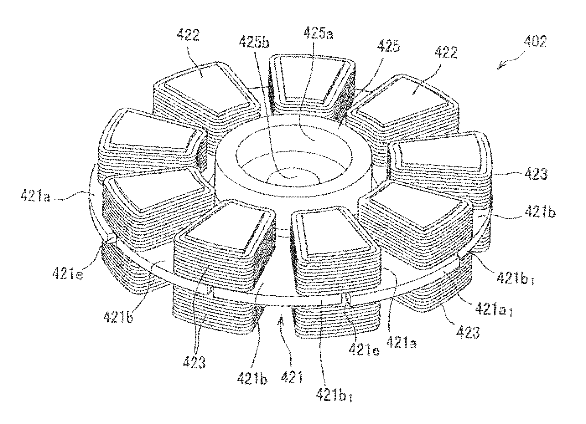
[0150]Incidentally, in the present embodiment, the outer side, with respect to the radial direction, of the disc basic portion region 421d (refer to FIG. 14) of the core holding member 421 divided along the circumferential direction CIR by the core holding regions 421a, 421b, however, without being limited thereto, the outer side, with respect to the radial direction, of the disc basic portion region 421d may have a mere shape of an annular disc region formed with holes or recessions 421c1, 421c2 substantially in a fan shape. In this case, it is unnecessary to provide notches 421e, and a shape whose outer circumferential portion is partially extending outward in a certain amount may be applied.
[0151]According to the present embodiment and the modification thereof, because the core holding member 421 is made of engineering plastic, an eddy current due to the rotation of the rotors 403A, 403B is not caused in the core holding member 421, which realizes ...
PUM
 Abstract
Description
Claims
Application Information