Apparatus for driving voltage controlled switching elements

a voltage control and switching element technology, applied in the direction of pulse technique, oscillation generator, power conversion system, etc., can solve the problems of large loss of switching element, inability to handle failure, and the voltage of the conduction control terminal coincides with the intermediate voltage, etc., to achieve favorable suppression of inconveniences

Active Publication Date: 2014-03-25
DENSO CORP
View PDF11 Cites 3 Cited by
  • Summary
  • Abstract
  • Description
  • Claims
  • Application Information

AI Technical Summary

Benefits of technology

[0008]Hence, it is desired to provide a driving device for switching elements, which drives voltage-controlled switching elements and is able to favorably suppress inconveniences ascribed to electrical surge occurring at the conduction control terminals of the switching elements.
[0010]In this configuration, a switching element of voltage control type is forcibly switched off (turned off) on condition that the voltage of the conduction control terminal corresponds to the intermediate voltage. Accordingly, the switching element is prevented from being kept switched on (turned on) in a region where loss of the switching element is large. Thus, the inconveniences ascribed to the electrical surge occurring at the conduction control terminal may be favorably suppressed.
[0019]In the above configurations, the soft-breaking discharge path is used to reduce the speed of switching the state of the switching element to an off-state. In this case, the occurrence of surge may be suppressed.
[0020]By way of example, the apparatus can have an off-state holding switching element that holds an off state of the switching element by short-circuiting an electrical connection between the conduction control terminal of the switching element and either an input terminal of an output terminal of the switching element, wherein the forcible switching-off means is configured to drive the off-state holding switching element for the forcible switching-off operation. In this configuration the off-state holding switching element is used to enhance the reliability of forced turn-off operation.

Problems solved by technology

In such a case, loss of the switching elements may become large and, further, drastic temperature rise may be caused accompanying generation of heat.
However, depending on the function of shutdown, for example, such a failure may not be handled because the current passing through the switching elements is maintained at a level equal to or less than a threshold.
The failure in which the voltage of the conduction control terminal coincides with the intermediate voltage may include a failure in which the voltage of the conduction control terminal is constantly maintained at the intermediate voltage, irrespective of whether the operation signal of the switching element is a switching-on command or a switching-off command.
However, in the failure as mentioned above, since the voltage of the conduction control terminal is at the level of the intermediate voltage, the current passing through the switching element is unlikely to become equal to or higher than a threshold current.
The failure in which the voltage of the conduction control terminal coincides with the intermediate voltage may include a failure in which the voltage of the conduction control terminal is constantly maintained at the intermediate voltage, irrespective of whether the operation signal of the switching element is a switching-on command or a switching-off command.
However, in the failure as mentioned above, since the voltage of the conduction control terminal is at the level of the intermediate voltage, the current passing through the driven switching element is unlikely to become equal to or higher than a threshold current.

Method used


Image

  • Apparatus for driving voltage controlled switching elements
  • Apparatus for driving voltage controlled switching elements
  • Apparatus for driving voltage controlled switching elements

Examples


first embodiment

[0043](First Embodiment)

[0044]With reference to the accompanying drawings, hereinafter are described some embodiments of a driving device for switching elements of the present invention. Referring first to FIGS. 1 to 4 and FIG. 5, a first embodiment of the present invention is described. In the first embodiment described below, the driving device for switching elements is applied to each driving device used in an inverter connected to a rotary machine as an on-vehicle main device.

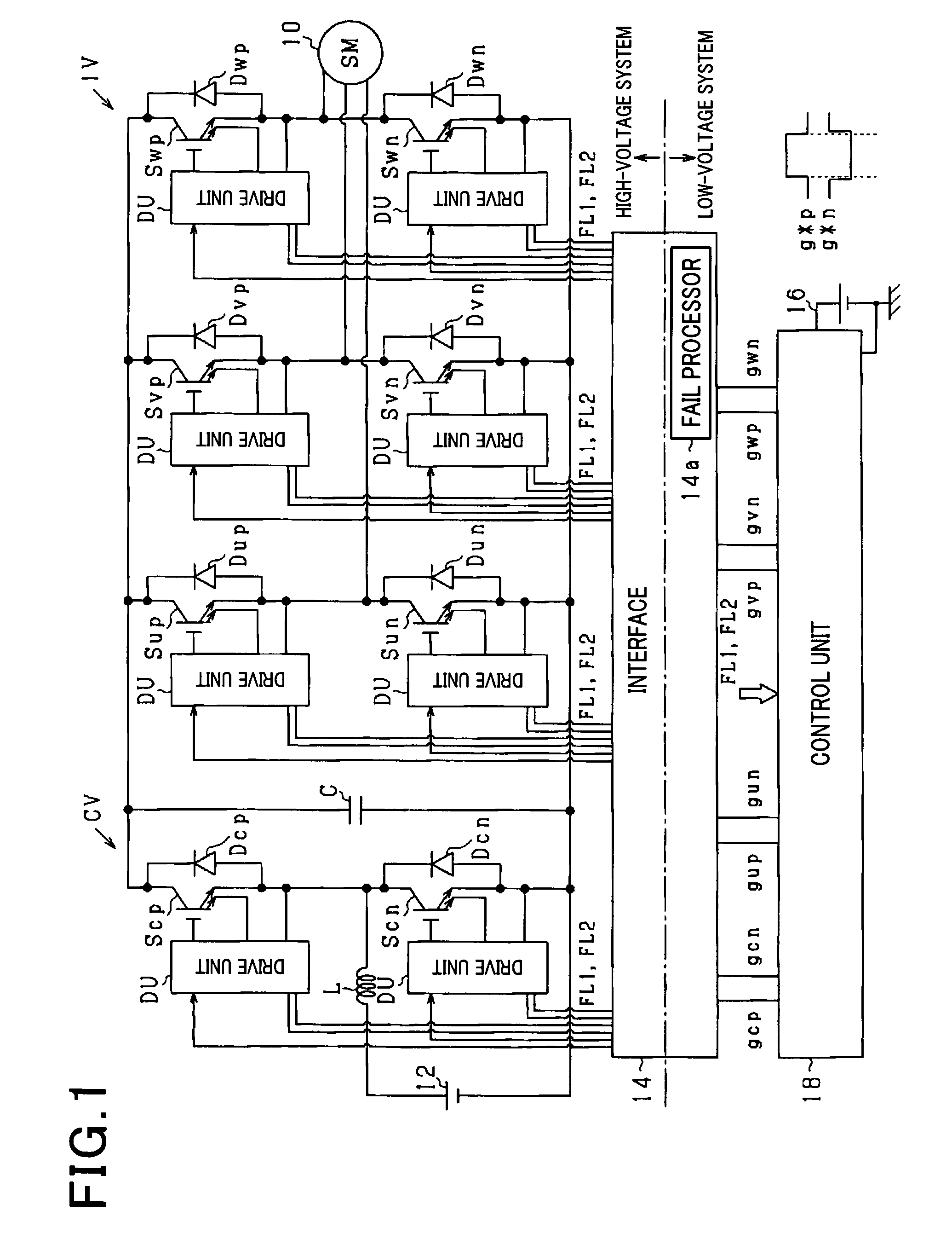
[0045]FIG. 1 is a general configuration of a control system according to the first embodiment. A motor generator 10 is an on-vehicle main device which is mechanically connected to drive wheels, not shown, of the vehicle. The motor generator 10 is connected to a high-voltage battery 12 via an inverter IV and a step-up converter CV,

[0046]The step-up converter CV includes a capacitor C, a pair of switching elements Scp and Scn connected parallel to the capacitor C, and a reactor L that connects a node of the p...

second embodiment

[0091](Second Embodiment)

[0092]Referring now to FIGS. 6 and 7, hereinafter is described a second embodiment of the present invention, focusing on the differences from the first embodiment described above. It should be appreciated that, in the second and the subsequent embodiments, the components identical with or similar to those in the first embodiment are given the same reference numerals for the sake of omitting unnecessary explanation.

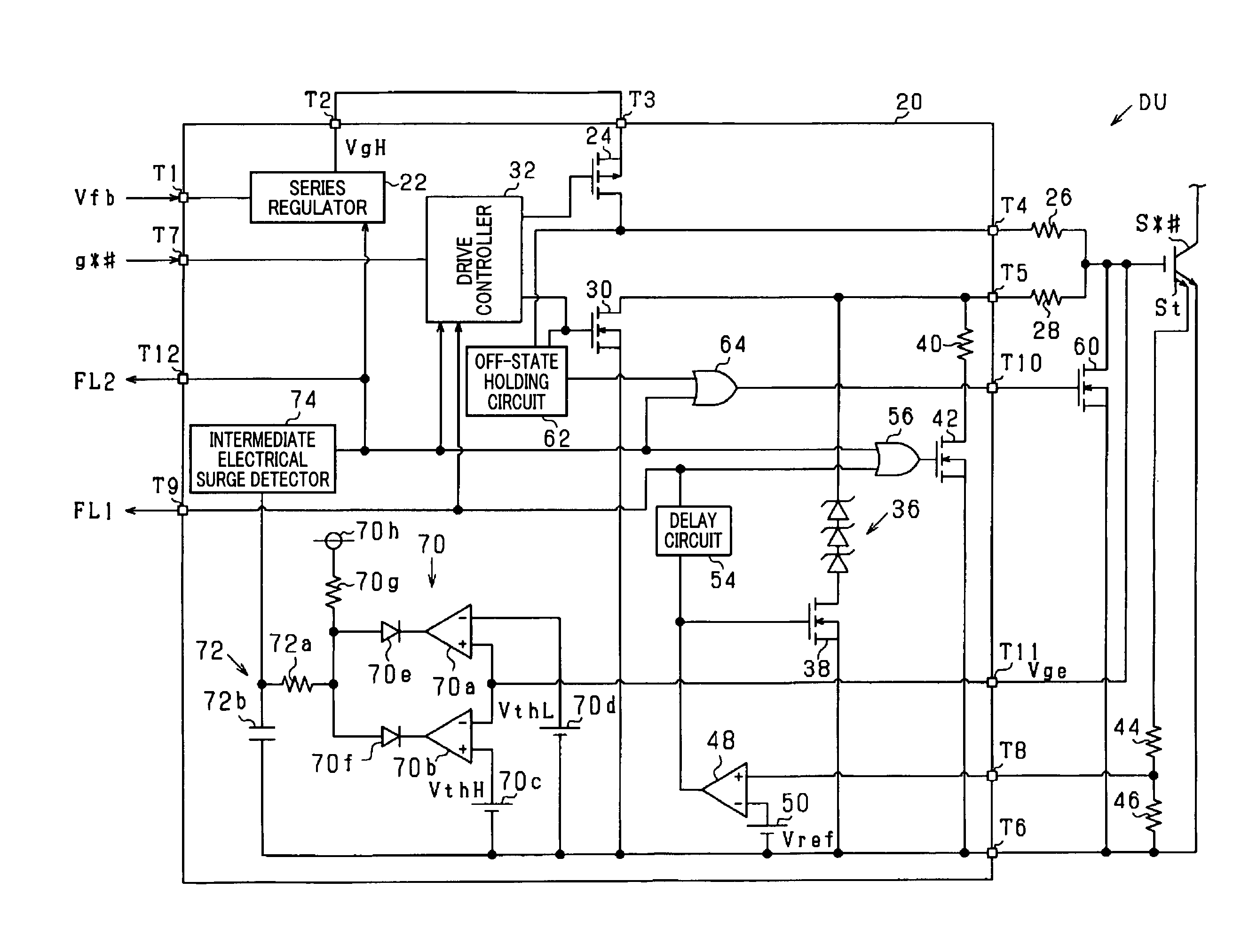
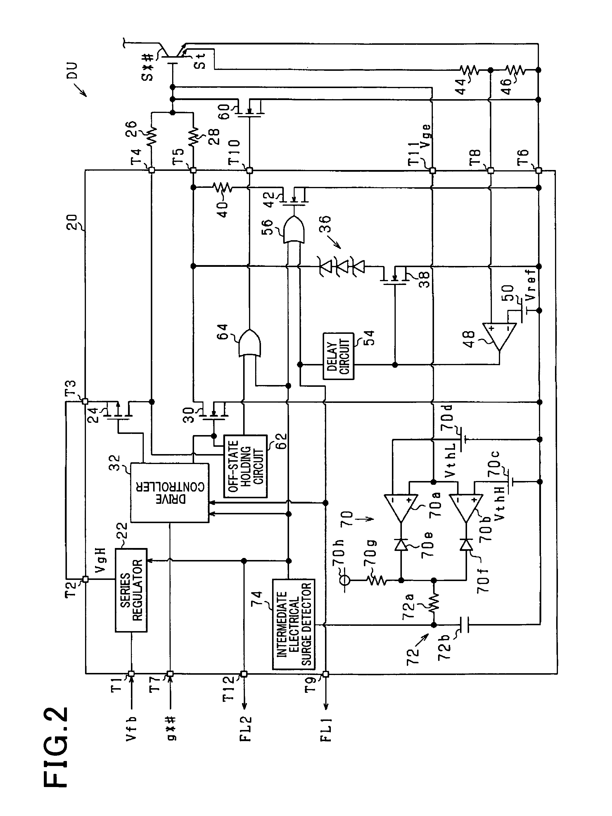
[0093]FIG. 6 illustrates a configuration of a drive unit DU according to the second embodiment.

[0094]As shown in FIG. 6, in the present embodiment, an output signal of the window comparator 70 is directly inputted to the intermediate electrical surge detector 74. The intermediate electrical surge detector 74 determines the occurrence or non-occurrence of intermediate electrical surge based on the output signal of the window comparator 70 and the operation signal g*#.

[0095]FIG. 7 illustrates a procedure, i.e. a series of steps, performed by the inte...

third embodiment

[0100](Third Embodiment)

[0101]Referring to FIG. 8, hereinafter is described a third embodiment of the present invention, focusing on the differences from the first embodiment described above.

[0102]FIG. 8 illustrates a configuration of a drive unit DU according to the third embodiment.

[0103]As shown in FIG. 8, the drive unit DU of the present embodiment includes a switch 80. The switch 80 switches the voltage applied to the gate of the switching element S*#, between an output voltage of the series regulator 22 and an input voltage of the series regulator 22. The switched condition is operated by the fail signal FL2. Specifically, when the fail signal FL2 is inputted, the voltage applied to the gate of the switching element S*# is switched to an input voltage of the series regulator 22.

[0104]Thus, when the gate voltage Vge is increased, the intermediate electrical surge will be eliminated. Accordingly, if the cause of the intermediate voltage is ascribed to factors 1 and 5 set forth a...


PUM


Abstract

An apparatus is provided to drive a voltage controlled switching element having a conduction control terminal. In the apparatus, it is determined whether or not voltage at the conduction control terminal is at a first voltage which is lower than a second voltage and which is equal to or more than a threshold voltage. The second voltage is a voltage provided when the switching element is in a normal on-state thereof. The threshold voltage is voltage at which the switching element is switched on. When it is determined that the voltage at the conduction control terminal is at the first voltage, the switching element is forcibly switched off.

Description

CROSS-REFERENCE TO RELATED APPLICATION[0001]This application is based on and claims the benefit of priority from earlier Japanese Patent Application No. 2010-169944 filed Jul. 29, 2010, the description of which is incorporated herein by reference.BACKGROUND OF THE INVENTION[0002]1. [Technical Field of the Invention][0003]The present invention relates to an apparatus for driving switching elements, and more particularly to the apparatus for driving the voltage-controlled switching elements.[0004]2. [Related Art][0005]It is known that this type of driving device is installed in a vehicle to drive switching elements configuring an inverter which is connected to an on-vehicle main device. For example, as disclosed in JP-A-2009-060358, this type of driving device has a function of shutting down an inverter when the current flowing through switching elements which are driven becomes equal to or more than a threshold current.[0006]The reason why the current flowing through switching elemen...

Claims


Application Information

Patent Timeline
Patent Type & Authority Patents(United States)
IPC IPC(8): H03K3/00
CPCH02M7/5387H02M1/08H02M1/32
Inventor FUKUTA, JUNICHIMAEBARA, TSUNEOMIURA, RYOTARO
Owner DENSO CORP
Why Eureka
Try Eureka