Touch panel and a method of locating a touch point of the same
a technology of touch panel and touch point, which is applied in the field of touch panel, can solve the problems of inability to improve the yield ratio of the touch panel, inability to reduce the cost and time of production, and inability to further upgrade the touch control precision of the conventional touch panel
- Summary
- Abstract
- Description
- Claims
- Application Information
AI Technical Summary
Benefits of technology
Problems solved by technology
Method used
Image
Examples
first embodiment
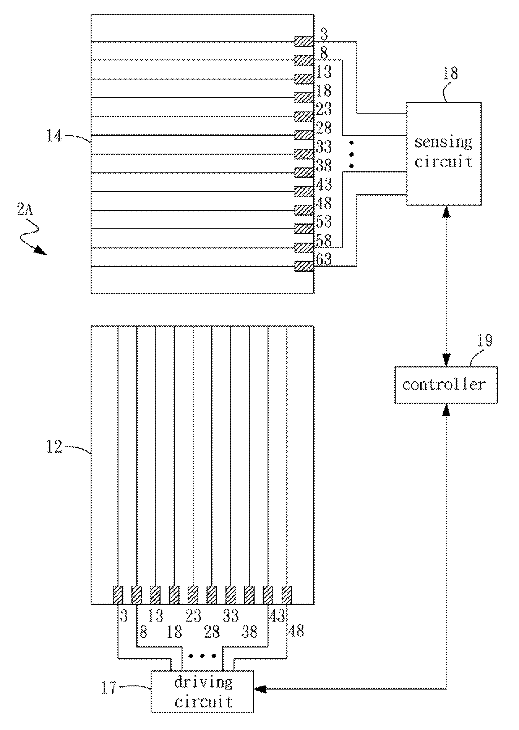
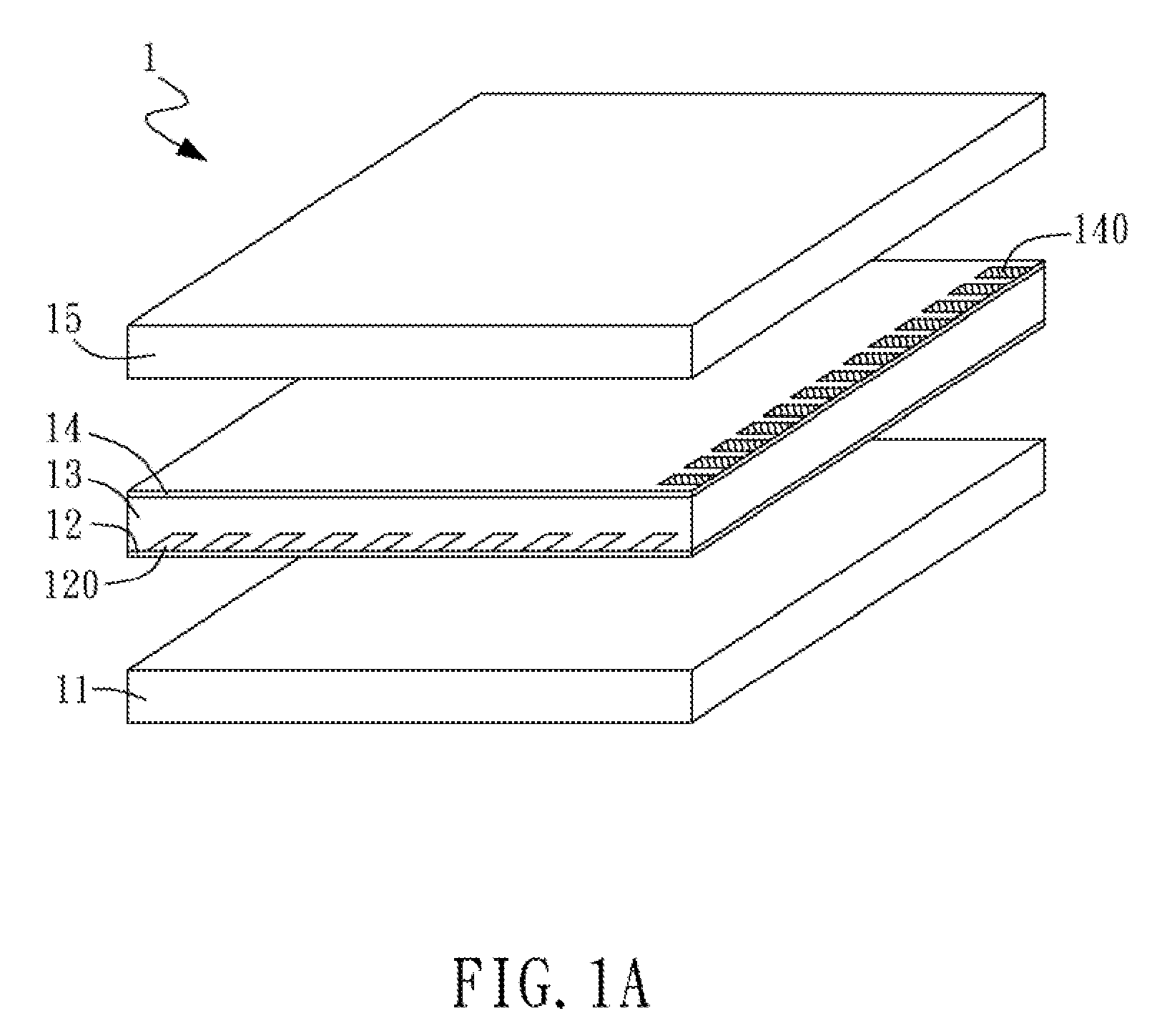
[0034]FIG. 2A shows a touch point locating system 2A of the touch panel of the present disclosure. The impedance of the first conductive film 12 along the second direction such as y-axis or a longitudinal axis is minimum and relatively less than the impedance along other directions. The impedance of the second conductive film 14 along the first direction such as x-axis or a transverse axis is minimum and relatively less than the impedance along other directions. Each first pad 120 connects to an electronic signal input circuit or a driving circuit 17 via conductive lines. The driving circuit 17 inputs electronic signals with the same pulse waveform or other waveforms to each first pad 120 in sequence or simultaneously. Each second pad 140 connects to an electronic signal readout circuit or a sensing circuit 18 via conductive lines to read out sensed electronic signals of each second pad 140. The first pad 120 is used as the driving electronic signal pad, while the second pad 140 is ...
second embodiment
[0036]FIG. 3A shows a touch point locating system 2B of the touch panel of the present disclosure. Similar to the touch point locating system shown in FIG. 2A, the impedance of the first conductive film 12 along the second direction such as y-axis or a longitudinal axis is minimum and relatively less than the impedance along other directions. The impedance of the second conductive film 14 along the first direction such as x-axis or a transverse axis is minimum and relatively less than the impedance along other directions. The differences are in that each second pad 140 connects to an electronic signal input circuit or a driving circuit 17 via conductive lines. The driving circuit 17 inputs electronic signals with the same pulse waveform or other waveforms to each first pad 140 in sequence or simultaneously. Each first pad 120 connects to an electronic signal readout circuit or a sensing circuit 18 via conductive lines to read out sensed electronic signals of each second pad 120. The...
PUM
 Abstract
Description
Claims
Application Information
 - R&D
- Intellectual Property
- Life Sciences
- Materials
- Tech Scout
- Unparalleled Data Quality
- Higher Quality Content
- 60% Fewer Hallucinations
Browse by: Latest US Patents, China's latest patents, Technical Efficacy Thesaurus, Application Domain, Technology Topic, Popular Technical Reports.
© 2025 PatSnap. All rights reserved.Legal|Privacy policy|Modern Slavery Act Transparency Statement|Sitemap|About US| Contact US: help@patsnap.com


