Terminal connection structure

a terminal connection and structure technology, applied in the direction of coupling contact members, coupling device connection, coupling/disassembly parts, etc., can solve the problems of increasing the size of the housing and the width of the housing, and achieve the effect of facilitating the connection to each other, and reducing the width of the terminal connection structur

Active Publication Date: 2014-04-01
YAZAKI CORP
View PDF8 Cites 8 Cited by
  • Summary
  • Abstract
  • Description
  • Claims
  • Application Information

AI Technical Summary

Benefits of technology

[0018]As explained above, the present invention according to the first aspect can set the relative position of the electric-contact portion of the first terminal fixture and the electric-contact portion of the second terminal fixture at the predetermined position. Thus, the terminal fixtures can be easily connected to each other without producing the variation in the electric resistance between the terminal fixtures.
[0019]Furthermore, the terminal fixtures can be connected to each other in a reliable manner even if the first terminal fixture and the second terminal fixture are arranged in parallel with an interval between each other. Thus, by arranging the first terminal fixture and the second terminal fixture in parallel with an interval between each other, the width of the terminal connection structure can be reduced compared to the case in which these terminal fixtures are arranged to lie in the same plane. Thus, the terminal connection structure can be downsized.
[0020]The present invention according to the second aspect can electrically-connect the first terminal fixture with the second terminal fixture in a reliable manner by sandwiching the terminal fixtures overlapped each other between the pair of contact pieces of the clip terminal. Thus, the terminal fixtures can be connected to each other in a reliable manner.
[0021]The present invention according to the third aspect can prevent the clip terminal from coming off with the clip terminal holder, thereby preventing the abrupt release of the connection of the terminal fixtures.

Problems solved by technology

However, the conventional terminal connection structure described above has a drawback that, since the housing is arranged such that the plurality of terminal fixtures lie in the same plane with respect to each other, the width of the housing becomes large, increasing the size of the housing.

Method used


Image

  • Terminal connection structure
  • Terminal connection structure
  • Terminal connection structure

Examples


Embodiment Construction

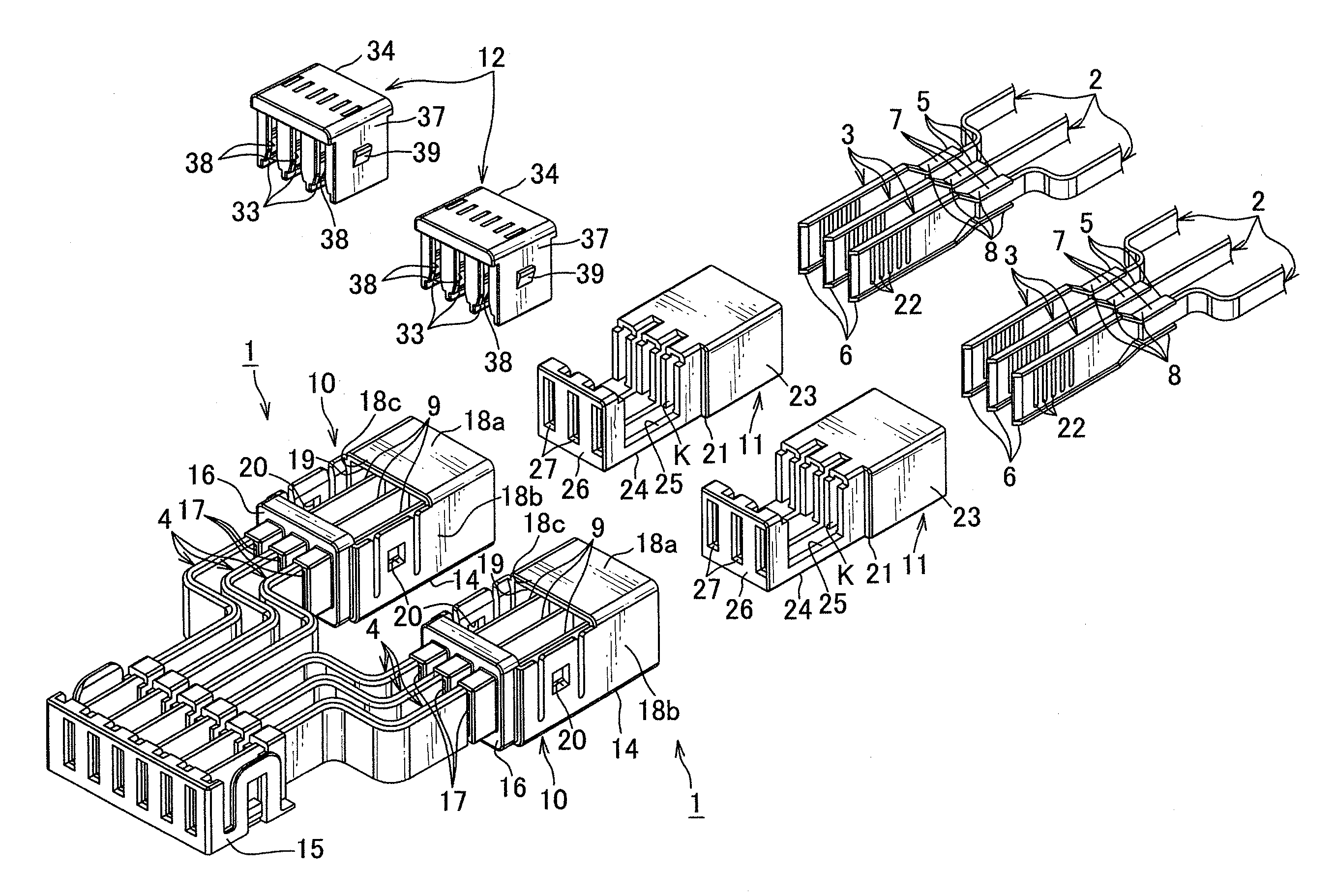
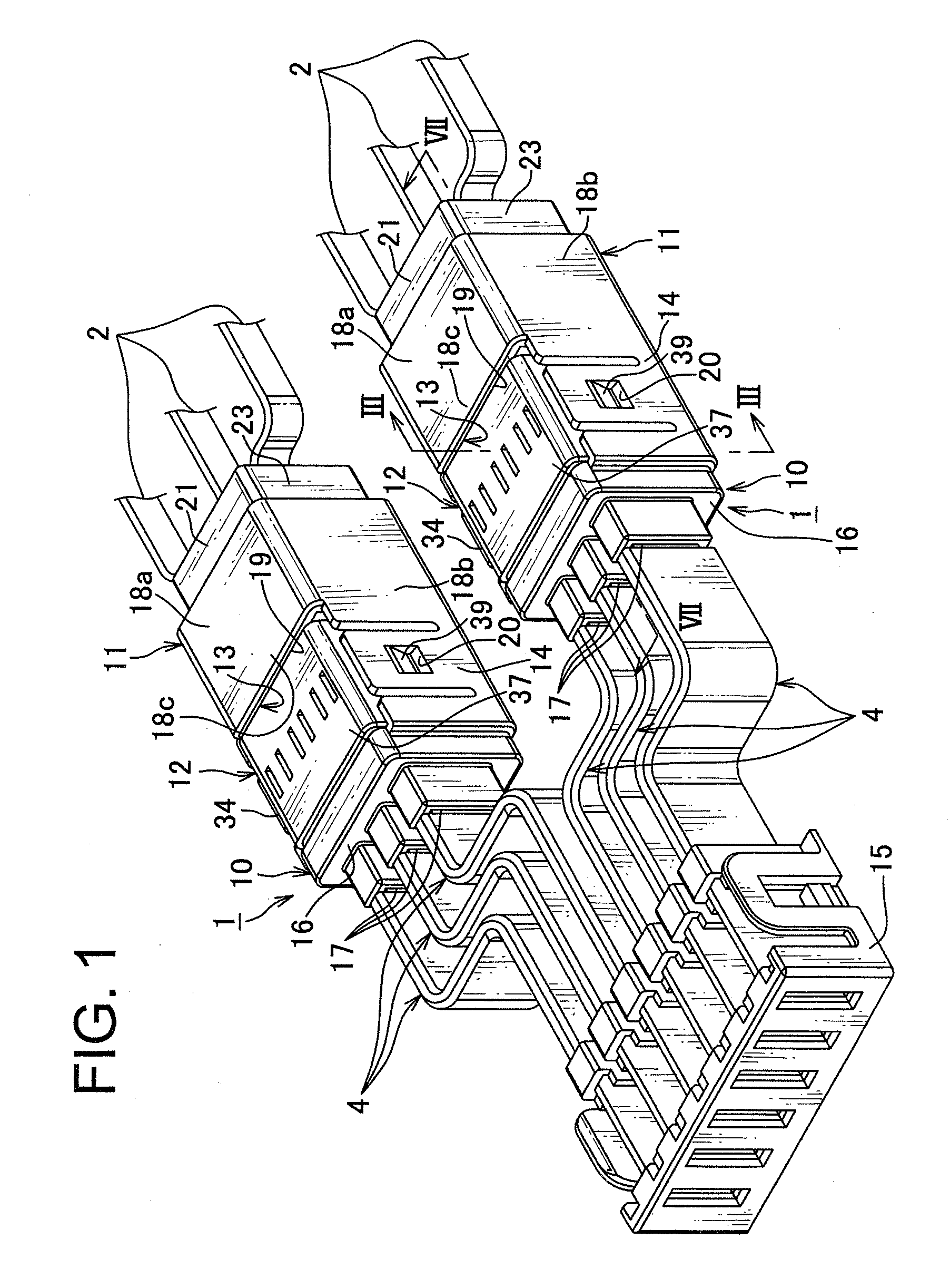
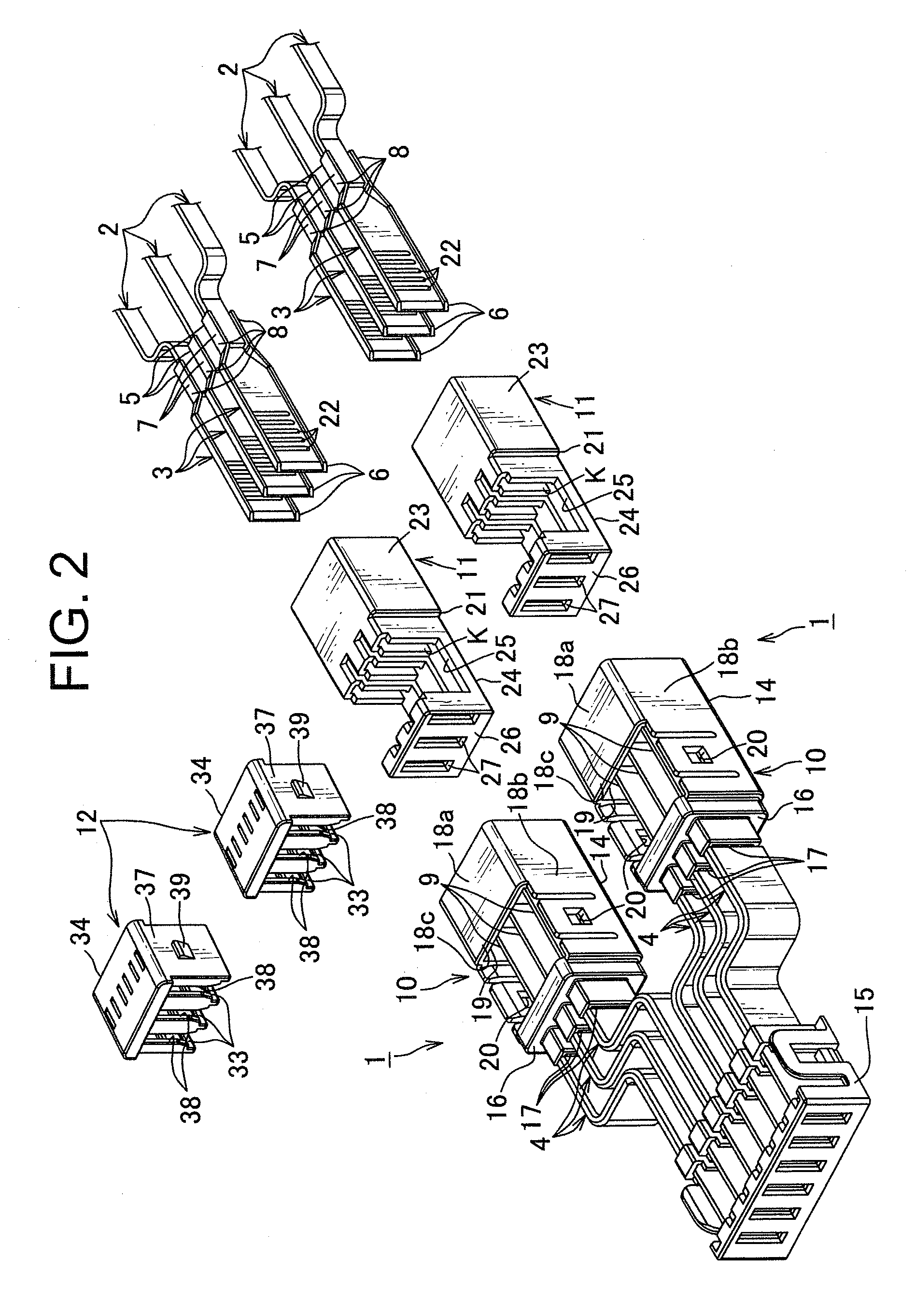
[0035]In the following, a terminal connection structure according to one embodiment of the present invention is explained in reference to FIGS. 1 through 12. As shown in FIGS. 1 and 2, a terminal connection structure 1 according to this embodiment is a terminal connection structure arranged to connect a thin-walled portion 9 as an electric-contact portion of a bus bar 4 as a first terminal fixture connected to an inverter as a power source device with an electric-contact portion 6 of a second terminal fixture 3 connected to a coil 2 of a motor as an another power source device. In the present invention, the power source is a device such as a battery, an inverter, a motor and a generator to which voltage for driving an automobile is applied.

[0036]The terminal connection structure 1 is a structure for connecting three bus bars 4 and three second terminal fixtures 3 together. The terminal connection structure 1 is arranged to connect the bus bar 4 and the second terminal fixture 3 to e...


PUM


Abstract

A terminal connection structure which is downsized and easily connects terminal fixtures together without producing variation in electric resistance therebetween. The terminal connection structure connects a bus bar connected to an inverter and a second terminal fixture connected to a motor coil. The terminal connection structure includes a first housing receiving a thin-walled portion of the bus bar, a second housing receiving an electric-contact portion of the second terminal fixture and having an insert portion, a clip terminal arranged to make the thin-walled portion closely contact with the electric-contact portion, and a permitting / restricting portion, which permits the clip terminal to be attached to one of the first housing and the second housing when the insert portion is at a predetermined position and restricts the clip terminal from being attached to one of the first housing and the second housing when the insert portion is not at the predetermined position.

Description

TECHNICAL FIELD[0001]The present invention relates to a terminal connection structure for connecting terminal fixtures to each other. Specifically, the present invention relates to a terminal connection structure for connecting power source devices to which voltage for driving an automobile is applied.BACKGROUND ART[0002]Currently, a hybrid vehicle and an electric vehicle which are driven by the rotational drive force of a motor have been used for the reduction in environmental burdens. These types of automobile, i.e. a hybrid vehicle and an electric vehicle and such driven by the rotational drive force of a motor, are mounted with power source devices such as a battery, an inverter, a motor and a generator to which drive voltage is applied. Due to the large voltage value of the electric current flowing between these power source devices, a thick cable which is thicker than an electric wire of a wire harness used for transmitting signal or distributing power to the respective electr...

Claims


Application Information

Patent Timeline
Patent Type & Authority Patents(United States)
IPC IPC(8): H01R13/15
CPCH01R13/193H01R2201/26H01R25/145H01R13/506H01R13/516H01R13/641
Inventor ADACHI, HIDEOMIKUBOSHIMA, HIDEHIKO
Owner YAZAKI CORP
Why Eureka
Try Eureka