Agglutination reaction system

a reaction system and agglutination technology, applied in the field of agglutination reaction system, can solve the problems of human error in such a test, complex detection system, and therefore high cost, and achieve the effect of reducing the cost of providing the system, and reducing the possibility of human error

Inactive Publication Date: 2014-04-01
PLATFORM DIAGNOSTICS LTD
View PDF32 Cites 1 Cited by
  • Summary
  • Abstract
  • Description
  • Claims
  • Application Information

AI Technical Summary

Benefits of technology

[0012]The present invention thus provides a system in which the test device and reader are separate, with the test device being releasably mountable in the reader for performance of an assay. This has the advantage that the test device may be a disposable single-use type device, but the reader element of the system, which is typically more complex and expensive to manufacture, does not have to be discarded at the same time. This not only enables the cost of providing the system to be lowered, but also enables improvements or alterations to be made to each component of the system without requiring replacement of the whole system. In addition, more sophisticated readers may be employed, and test devices may be provided in bulk with a single reader.
[0013]By employing a reader, the system of the invention enables the results of the system to be obtained in a non-visual manner, thus reducing the possibility of human error in reading the results directly from a test device.
[0014]Agglutination based assays of the present invention include assays for detecting the presence, absence or amount of an analyte based upon agglutination caused upon contact of a sample with agglutination reagents. In the present invention, the agglutination based assay is carried out in a capillary pathway which receives the sample and reagent. The reagents include both the agglutination reagents and any other agents (such as buffers) necessary for the assay. The latter include, for example, an electrolyte (either solid, causing the liquid to become conductive upon dissolution, or pre-dissolved, in the form of a buffer) or fluids which aid flow of reagents / sample along the capillary pathway, or increase the volume of the sample. Suitable fluids include buffers such as PBS pH 7.4, and physiological saline.
[0025]The reader comprises detection means for determining the presence or absence of sample at pre-determined positions in the capillary pathways, herein defined as detection regions. The detection means used in the present invention are non-visual, meaning that presence or absence of sample at the detection regions is determined by means other than the naked eye. This reduces the effect of human error, and also, in a point-of-care environment, means that continued monitoring during the performance of an assay by the user is not necessary. Further, the result is permanent and stable.

Problems solved by technology

Whilst these assays are sensitive, the detection systems are complex, and therefore expensive.
Typically, the detection systems require several washing steps, meaning that the assays are generally unsuitable for point-of-care type assessment.
However, there is room for human error in such a test, due to reliance on the user to correctly read and interpret the visual result.
The assay is also reliant upon the agglutination causing a total blocking of the capillary, therefore erroneous results may arise if the agglutination reaction is weak or if the sample volume is insufficient to fill all the capillaries.
Also, the result may be unstable, yielding a different result if read at a later time.

Method used


Image

  • Agglutination reaction system
  • Agglutination reaction system
  • Agglutination reaction system

Examples


Embodiment Construction

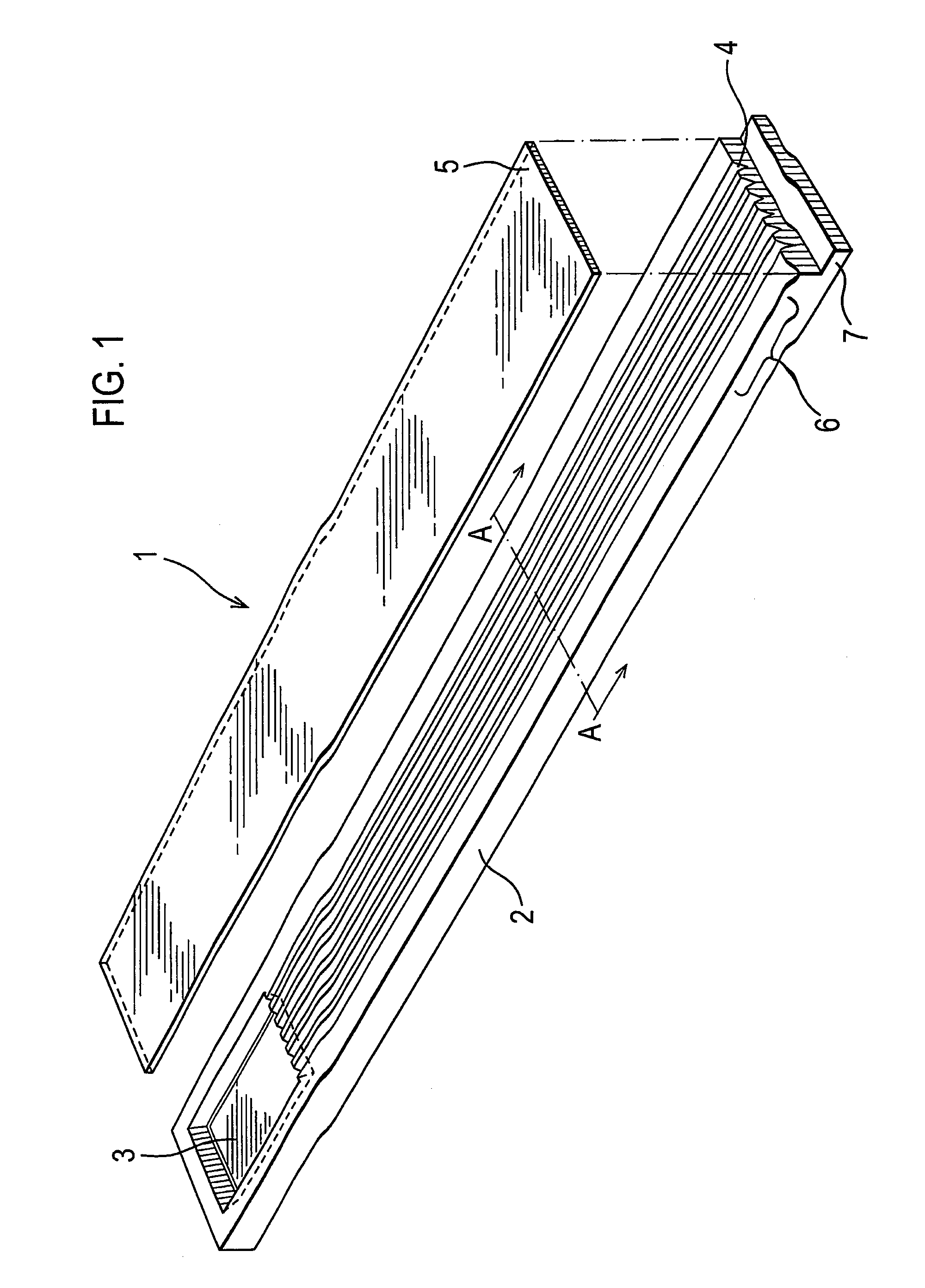
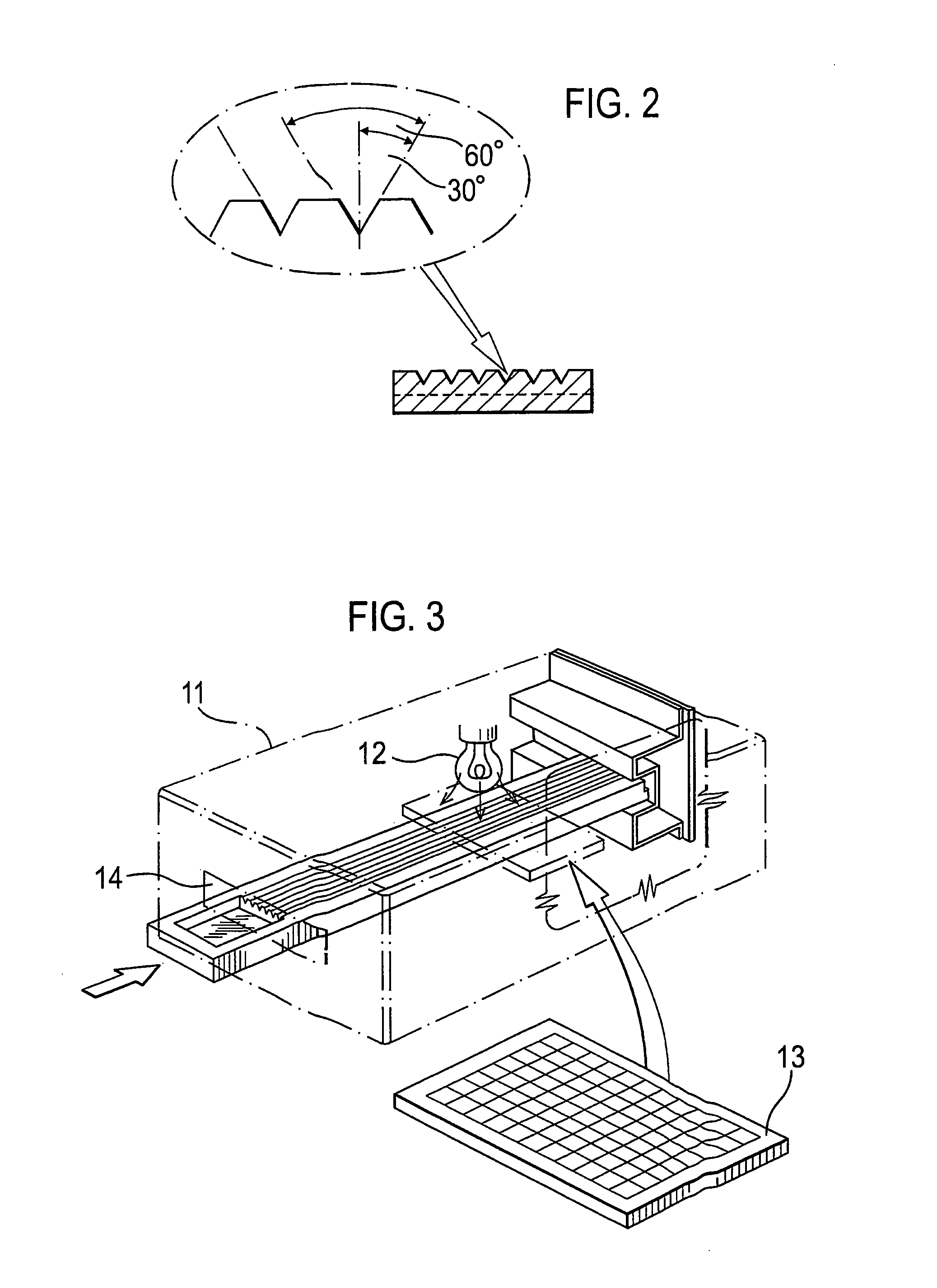
[0067]The test device 1 illustrated in FIG. 1 comprises a moulded, light transparent (clear) body 2 having upper and lower major surfaces. The upper surface is moulded towards one end thereof with a sample well 3 from which extend in parallel a plurality of V-shaped pathways 4 also moulded in the upper surface. As shown in FIG. 2, each such pathways 4 has an apical angle of 60° with each side (as viewed in section) being of equal length, preferably in the range of 0.1-1.3 mm. The pathways 4 are intended to provide two sides of a triangular capillary pathway that is completed by a cover sheet 5 which is adhesively bonded to the body 2. This cover sheet may, for example, be a polyester membrane and is bonded to the body 2 by means of an adhesive of the type described more fully above. With the cover sheet in position, blood introduced into the sample well 3 is able to flow (by capillary action) towards the downstream ends of the capillary pathways.

[0068]Body 2 may be of a hydrophobic ...


PUM

PropertyMeasurementUnit
pHaaaaaaaaaa
lengthaaaaaaaaaa
lengthaaaaaaaaaa

Abstract

The present invention provides an agglutination based assay system for determining the presence and / or amount of analyte in a sample comprising a test device having one or more capillary pathways comprising detection regions adapted for non-visual detection of a sample which is releasably engageable with a reader which comprises detection means for detecting the sample at the detection regions in each of said capillary pathways and electronic means for indicating the presence and / or amount of analyte.

Description

REFERENCE TO RELATED APPLICATIONS[0001]This application is a continuation of International Patent Application No. PCT / GB2005 / 004166, filed Oct. 28, 2005, which claims priority to UK Patent Application No. 0423885.3, filed Oct. 28, 2004.INTRODUCTION[0002]The present invention relates to an agglutination based assay system for detection of analyte in a sample. Also provided are a test device and reader of the assay system, and an assay method using the system, and kits comprising components of the invention.BACKGROUND TO THE INVENTION[0003]Immunoassays, and in particular techniques such as the radioimmunoassay and enzyme immunoassay, have revolutionised diagnostic medicine. Such assays are based upon the detection of antibody-antigen interactions. Numerous detection systems are available, including the use of enzyme labelled antigens, antibodies or complexes thereof, which require incubation with specific substrates in order to measure the end-point either colour metrically or floures...

Claims


Application Information

Patent Timeline
Patent Type & Authority Patents(United States)
IPC IPC(8): G01N33/80C12M1/34G01N33/53G16H10/40G16H50/20
CPCG01N33/80G01N33/5304G06Q50/24G16H10/40G16H50/20
Inventor MINTER, STEPHEN JOHNBOND, DAMIAN JOSEPH PETERRUDDELL, CAROLYN JENNIFER
Owner PLATFORM DIAGNOSTICS LTD
Why Eureka
Try Eureka