Axle lift assembly

a technology for axle lifts and components, applied in suspensions, vehicle springs, resilient suspensions, etc., can solve the problems of increasing the cost of roadway tolls, inefficient pulling such trailers, and expensive to own and maintain several vehicles and trailers, and achieve the effect of eliminating the upward force on the air springs

Active Publication Date: 2014-04-15
SAF HOLLAND INC (US)
View PDF16 Cites 28 Cited by
  • Summary
  • Abstract
  • Description
  • Claims
  • Application Information

AI Technical Summary

Benefits of technology

[0004]According to one aspect of the present invention, an axle lift assembly includes a beam slidably coupled with a longitudinal extent of a vehicle frame. A trailing arm has a first end pivotably coupled with the beam. An axle is rotatably coupled with an intermediate portion of the trailing arm. An air spring is disposed between a second end of the trailing arm and the beam for r...

Problems solved by technology

However, it can be inefficient to pull such a trailer when the additional tires are unnecessary to disperse a light load, given that added tires increase friction and...

Method used


Image

  • Axle lift assembly
  • Axle lift assembly
  • Axle lift assembly

Examples


Embodiment Construction

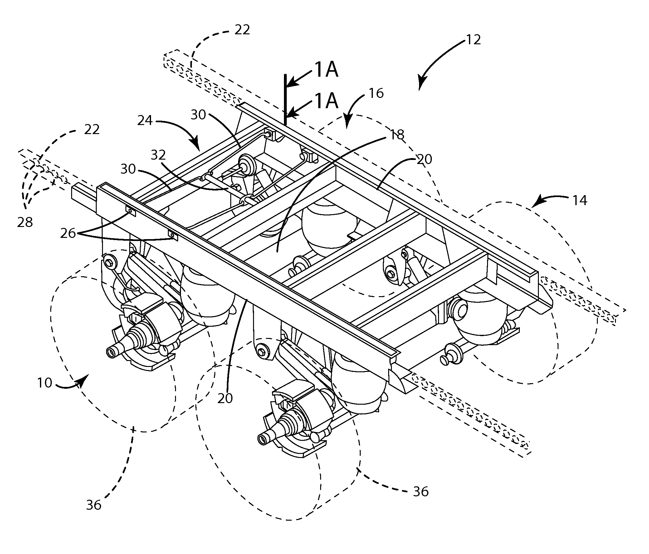
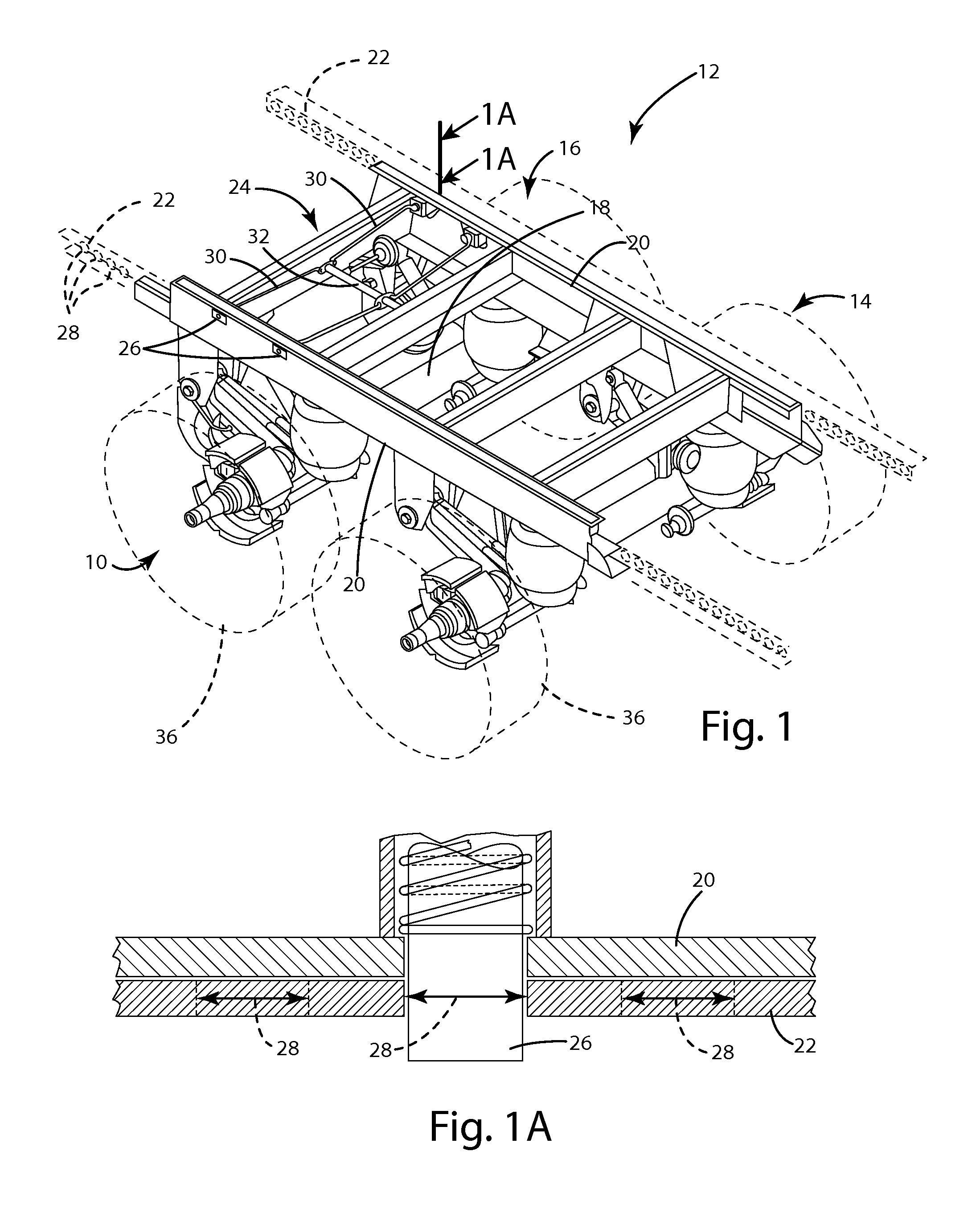
[0023]For purposes of description herein, the terms “upper,”“lower,”“right,”“left,”“rear,”“front,”“vertical,”“horizontal,” and derivatives thereof shall relate to the invention as oriented in FIG. 1. However, it is to be understood that the invention may assume various alternative orientations, except where expressly specified to the contrary. It is also to be understood that the specific devices and processes illustrated in the attached drawings, and described in the following specification are simply exemplary embodiments of the inventive concepts defined in the appended claims. Hence, specific dimensions and other physical characteristics relating to the embodiments disclosed herein are not to be considered as limiting, unless the claims expressly state otherwise.

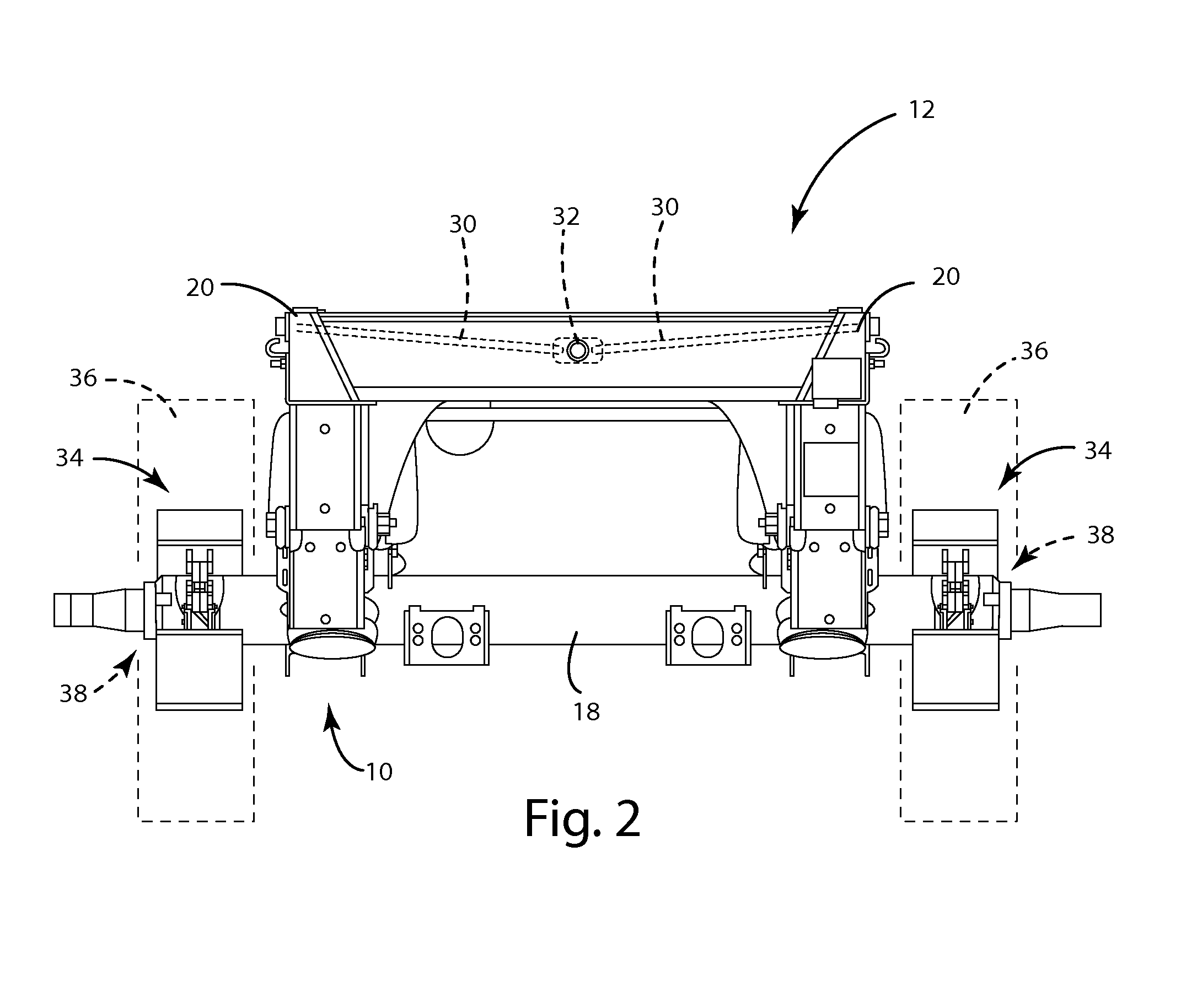
[0024]Referring to FIG. 1, the reference number 10 generally designates an axle lift assembly of the present invention. In the illustrated embodiment, the axle lift assembly 10 is shown on a tandem axle assembly 12 that ...


PUM


Abstract

An axle lift assembly includes a beam slidably coupled with and extending on a longitudinal extent of a vehicle frame. A trailing arm has a first end pivotably coupled with the beam. An axle is rotatably coupled with an intermediate portion of the trailing arm. An air spring is disposed between a second end of the trailing arm and the beam for absorbing an upward force from the axle. A support bracket extends down from the beam proximate the first end of the trailing arm. A pneumatic actuator is disposed between the support bracket and the trailing arm for raising the axle from a deployed position to a retracted position that substantially eliminates the upward force on the air spring from the axle.

Description

CROSS-REFERENCE TO RELATED APPLICATIONS[0001]This application claims priority under 35 U.S.C. §119(e) to, and the benefit of, U.S. Provisional Patent Application No. 61 / 767,029, entitled “AXLE LIFT ASSEMBLY,” filed on Feb. 20, 2013, the entire disclosure of which is hereby incorporated by reference.FIELD OF THE INVENTION[0002]The present invention generally relates to an axle lift assembly, and more particularly, to an axle lift assembly for a vehicle that, in one embodiment, is longitudinally slidable relative to a chassis of the vehicle and actuatable based on weight of a load carried by the vehicle.BACKGROUND OF THE INVENTION[0003]As businesses attempt to optimize inventory levels to meet variable demand, it is common for modern industrial vehicles, including trucks and trailers, to be used for shipping a wide variety of load types and configurations. In general, it is advantageous to alter a vehicle's carrying capacity by adding or removing trailers from the vehicle or using alt...

Claims


Application Information

Patent Timeline
IPC IPC(8): B62D61/12
CPCB62D61/12B62D61/125B60G2204/143B60G2400/90B60G2400/204B60G2400/52B60G11/27B60G2206/601B60G17/018B60G7/02B60G11/28B60G2200/31B60G2204/43B60G2204/4702B60G2400/30B60G2202/152B60G2400/51222B60G2204/4302B60G17/016B60G2204/126B60G17/0155B60G5/00
Inventor KAREL, JONATHONHICKS, WILLIAMGREER, GARY
Owner SAF HOLLAND INC (US)
Why Eureka
Try Eureka