
Fork cartridge driver

a technology for forks and drivers, applied in the field of forks, can solve the problems of affecting the service life of the fork, the owners' undesirable scratching of the anodizing, and the function of the modern suspension is becoming increasingly complicated, so as to reduce the potential damage of parts, reduce the slipping of the tool, and facilitate the grip

Active Publication Date: 2014-04-22
MOTION PRO
View PDF4 Cites 11 Cited by
  • Summary
  • Abstract
  • Description
  • Claims
  • Application Information

AI Technical Summary

Benefits of technology

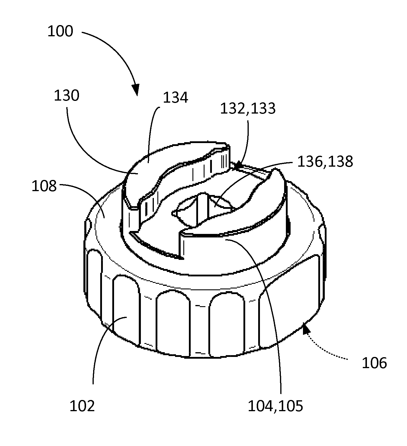
The present invention is a fork cartridge driver that has a reversible inner driver that can engage and manipulate both the fork cartridge and the fork cap. It includes an outer ring that can engage the fork cap while the inner driver can engage the fork cartridge, and can be easily clamped to protect its finish. The outer ring has a knurled surface for easier gripping and a flat surface area for more secure clamping. The tool mates securely with the parts, reducing slipping and potential damage. The invention simplifies the removal operation and reduces the number of tools required.

Problems solved by technology

Modern suspension is becoming increasingly complicated both in function and servicing.
Much care must be taken during this process as the parts are delicate and often are anodized.
Scratching the anodizing is undesirable to the owners.
Motorcycle repair shops commonly use sets of socket wrenches with a ratchet handle for mechanical operations, but the ridge on the top of the fork cartridge generally requires a different tool, which may require some effort to locate, thus wasting time.
However, there are several problems with using the existing tool as described above: 1) the ridge 52 on the fork cartridge rises only about 2 mm above the height of the top of the fork cap when assembled and thus provides a very limited purchase for attachment of the existing tool to the ridge 52.
This is difficult and time consuming to do, and often ends in frustration and damage to the fork cap and or the fork cartridge.
However, the problem with this method is that the elongated hexagonal shape of the ridge 52 only allows the socket wrench to engage two of the points in the socket, with very limited contact area and does not provide a very secure grip on the fork cartridge ridge 52 (a hex socket normally engages six flats on a hex head to provide many more times the contact area).
If the tool slips as torque is applied, this could easily result in damage to the fork cartridge, which once damaged cannot be repaired.
The manufacturer does not offer replacement fork caps or cartridges separately and requires that the entire assembly be purchased together at a cost of several hundred dollars.

Method used


Image

  • Fork cartridge driver
  • Fork cartridge driver
  • Fork cartridge driver

Examples


Embodiment Construction

[0036]The present invention is a fork cartridge driver, which will be referred to by the reference number 100, and thus shall be referred to as cartridge driver 100. A preferred embodiment of the cartridge driver 100 is illustrated in FIGS. 4-10.

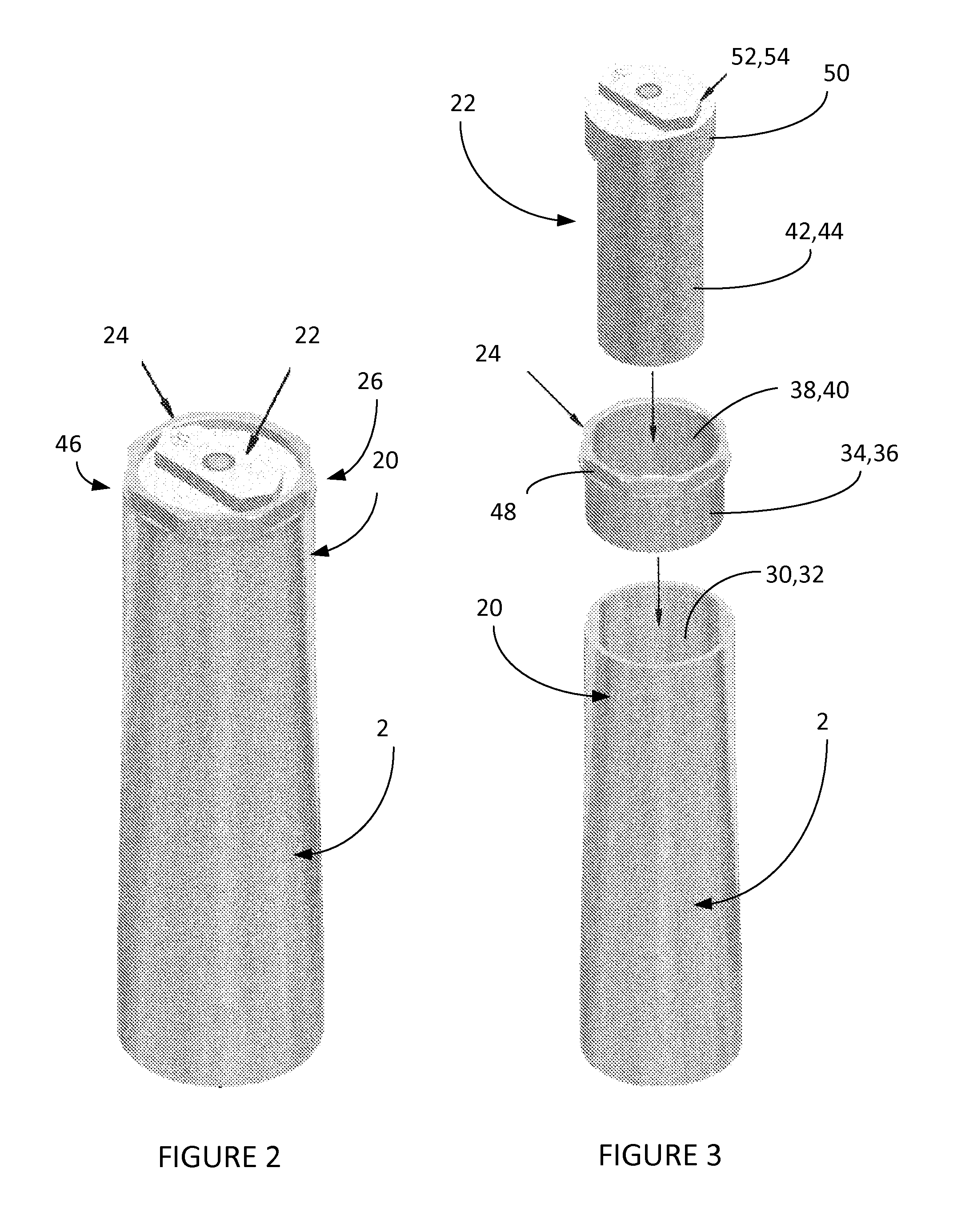
[0037]Modern motorcycle suspensions are becoming increasingly complicated both in function and servicing. The newer style forks have separated oil chambers for rebound and compression. A common configuration used on motorcycles includes a fork cartridge which is filled with oil, and this fork cartridge is then fitted within the fork tube as seen in FIG. 2. The fork cartridge is screwed into the inner bore of a fork cap, and then this fork cap is screwed into the bore of a fork tube. In order to remove or replace the oil, it is then a 2-stage process as the fork cap and fork cartridge are removed together from the fork tube, and then the fork cap is removed from the fork cartridge.

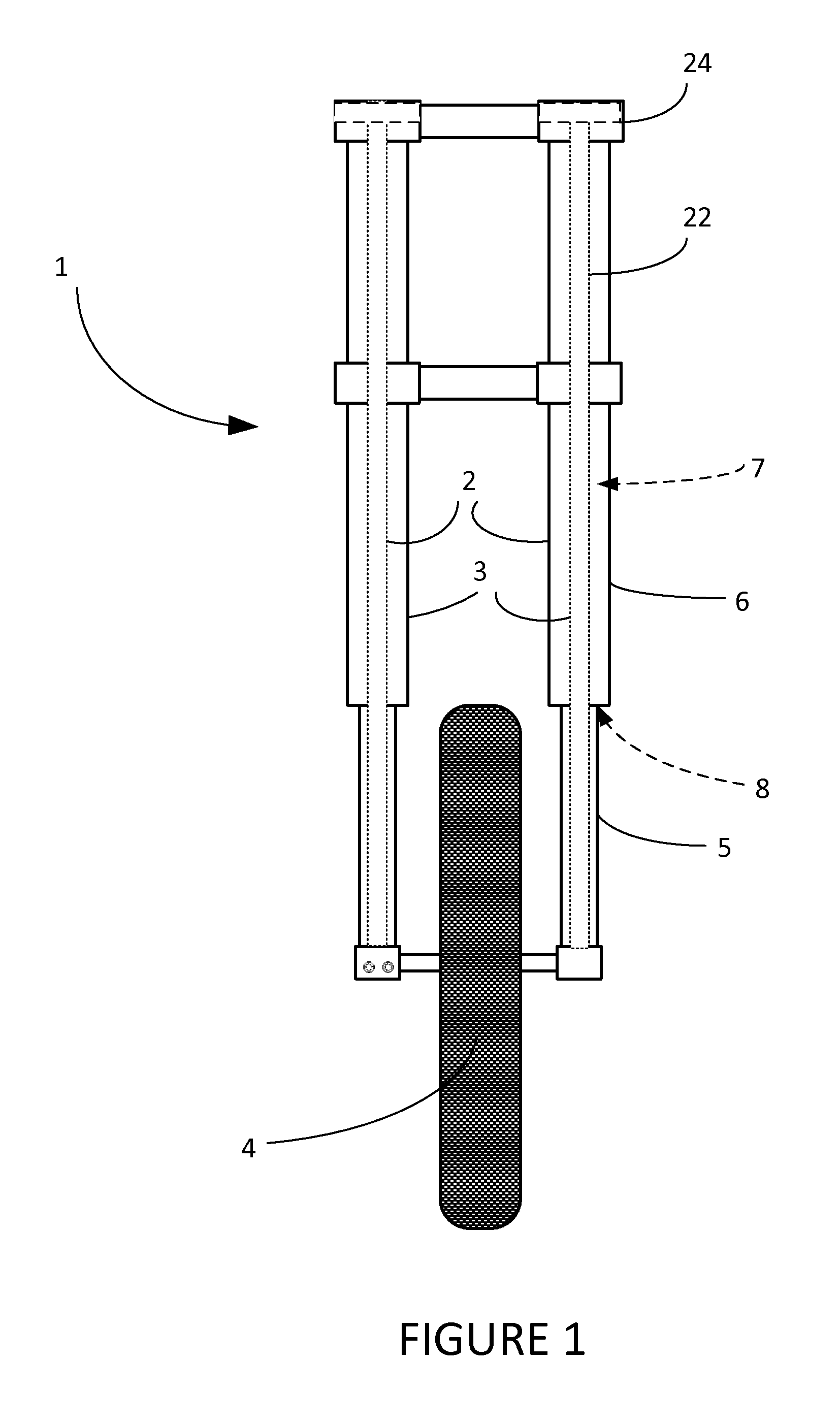
[0038]FIG. 1 shows a front view of a motorcycle 1 showing the ...


PUM

PropertyMeasurementUnit
thickaaaaaaaaaa
heightaaaaaaaaaa
thicknessaaaaaaaaaa

Abstract

A fork cartridge driver having an outer ring and an inner driver which is reversible to engage both a fork cap and a fork cartridge. Also a second embodiment of a fork cartridge driver having an enclosed slot. Also a third embodiment of a fork cartridge driver having an engagement feature mate. Also a method for disassembling a fork cartridge assembly, which includes a fork cap having an octagonal outline portion and a fork cartridge having a ridge using a fork cartridge driver which is reversible.

Description

[0001]The following non-provisional patent application claims priority to provisional application No. 61 / 466,404 entitled Fork Cartridge Driver to the same inventor.TECHNICAL FIELD[0002]The present invention relates generally to devices for repairing mechanical parts and more particularly to tools for servicing or replacing the oil in the fork of a motorcycle.BACKGROUND ART[0003]The front wheel of a motorcycle is usually linked to the frame by a pair of fork tubes. These tubes house the front suspension and usually include springs and compartments filled with fork oil to act as a shock absorber, which protects the rider from bumps and vibrations as the vehicle travels uneven surfaces. The most common form of fork commercially available is a telescopic fork which uses fork tubes which contain the suspension components (coil springs and damper) internally. This design is simple and inexpensive to manufacture, and relatively light compared to designs based on external components and li...

Claims


Application Information

Patent Timeline
Patent Type & Authority Patents(United States)
IPC IPC(8): B25B13/48B25B13/00B62K25/06B25B13/02B25B13/06
CPCB25B13/065B62K25/06B25B13/48B25B13/00Y10T29/49822
Inventor SCOTT, STEVEN, RICHARD
Owner MOTION PRO
Learn More