
Arrangement and method for efficient combustion of fuel in a combustion engine

a combustion engine and fuel arrangement technology, which is applied in the direction of machines/engines, mechanical equipment, electric control, etc., can solve the problems of rapid deceleration of fuel injected into the combustion space by the gaseous medium, and achieve the effects of shortening the load, good characteristics, and easy controllability

Active Publication Date: 2014-04-22
SCANIA CV AB
View PDF8 Cites 1 Cited by
  • Summary
  • Abstract
  • Description
  • Claims
  • Application Information

AI Technical Summary

Benefits of technology

The present invention combines the benefits of an HCCI engine with a diesel engine's ease of control and reduced wear on components. It does this by injecting fuel into a combustion space at a high velocity to create a premixed flame and reduce emissions. Fuel is injected for a period of time to allow it to mix with the gaseous medium and burn before igniting. Adding fuel at multiple times in quick succession reduces stress and wear on components. The method can be controlled by the time of fuel injection, making it easy to control like a diesel engine.

Problems solved by technology

However, fuel injected into a combustion space is subject to rapid deceleration by the gaseous medium.

Method used


Image

  • Arrangement and method for efficient combustion of fuel in a combustion engine
  • Arrangement and method for efficient combustion of fuel in a combustion engine
  • Arrangement and method for efficient combustion of fuel in a combustion engine

Examples


Embodiment Construction

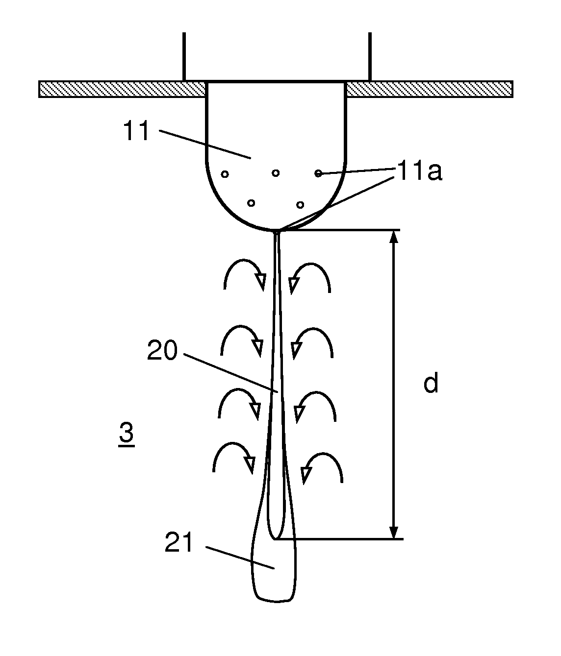
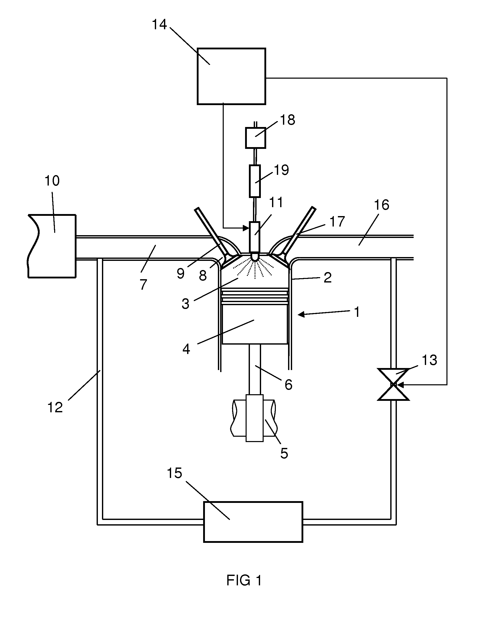
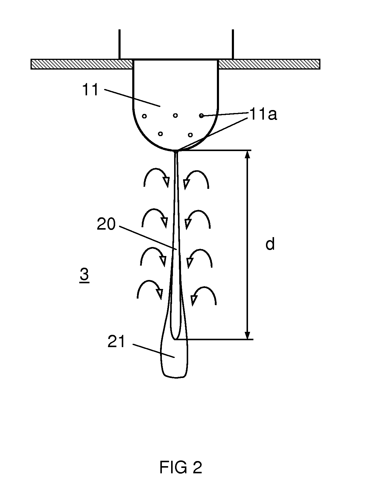
[0017]FIG. 1 depicts a cylinder 2 of a supercharged combustion engine 1. The cylinder 2 comprises a combustion space 3 bounded downwards by a movable piston 4. The piston 4 is connected to a crankshaft 5 by a connecting rod 6. The movements of the piston 4 in the cylinder 2 are converted to rotary motion by the crankshaft 5. The combustion engine 1 may comprise any desired number of such cylinders 2. An inlet line 7 is connected via an aperture 8 to the combustion space 3 to make it possible to supply compressed air to the combustion space 3. An inlet valve 9 is arranged in the aperture 8 to control the supply of air to the combustion space 3. A charge air cooler 10 is arranged in the air line 7 to cool the air before it is led into the combustion space 3. The inlet line 7 is connected to a return line 12 for recirculation of exhaust gases. The return line 12 comprises an EGR valve 13 by which it is possible to recirculate a desired amount of exhaust gases to the inlet line 7. The r...


PUM


Abstract

In a combustion space of a combustion engine, an inlet valve to supplies a gaseous medium which contains oxygen to the combustion space. A movable piston to compress the gaseous medium in the combustion spaces. An injector injects fuel in the combustion space in a jet which comprises a multiplicity of small fuel drops. The injector injects fuel in the combustion space at such a high initial velocity that the fuel injected in the jet mixes with the gaseous medium to form a substantially homogeneous mixture before the mixture has been decelerated to a velocity at which the fuel ignites and burns. Devices may cool the gaseous medium and the fuel before entry into the combustion space.

Description

CROSS REFERENCE TO RELATED APPLICATION[0001]The present application is a 35 U.S.C. §§371 national phase conversion of PCT / SE2008 / 050158, filed Feb. 11, 2008, which claims priority of Swedish Application No. 0700380-9, filed Feb. 15, 2007, the disclosure of which is incorporated by reference herein. The PCT International Application was published in the English language.BACKGROUND OF THE INVENTION, AND STATE OF THE ART[0002]The present invention relates to an arrangement and a method for efficient combustion of fuel in a combustion engine by controlled injection of the fuel.[0003]The type of combustion engines commonly known as HCCI (Homogenous Charge Compression Ignition) engines may be regarded as a combination of an Otto engine and a diesel engine. In HCCI engines, fuel and air are mixed in a combustion space to form a homogeneous lean mixture. The fuel mixture is compressed until it is self-ignited by compression heat. In this situation, the combustion takes place with a so-calle...

Claims


Application Information

Patent Timeline
Patent Type & Authority Patents(United States)
IPC IPC(8): F02B3/08F02M45/00
CPCY02T10/123F02B2275/14F02D41/40F02B1/12Y02T10/44F02D41/3035F02M25/0727F02M61/182F02M26/23Y02T10/12Y02T10/40F02B3/08F02M45/00
Inventor HOKKANEN, VESADAHLEN, LARSHOLMBORN, JONASCRONHJORT, ANDREAS
Owner SCANIA CV AB
Learn More