Active electric torsional vibration damper and method to realize the same

a technology of vibration damper and active electric torsional, which is applied in the direction of shock absorber, damper with inertia effect, mechanical apparatus, etc., can solve the problems of increasing the manufacture increasing the manufacturing cost and design difficulty, and the method is comparatively low cost. , the effect of reducing the cost of the main machinery

Inactive Publication Date: 2014-04-29
LUO QING
View PDF10 Cites 3 Cited by
  • Summary
  • Abstract
  • Description
  • Claims
  • Application Information

AI Technical Summary

Benefits of technology

[0009]The present invention aims to provide an active electric torsion damper and a method to realize the same. The damper produces an anti-torsion by electromagnetic excitation that is opposite to torsional-vibration direction of the shaft on a rotating machinery to eliminate the torsional vibration of the shaft.
[0018]A method to realize the active electric torsional vibration damper comprising following steps:Step 1, assemble conducting coils on a stationary device and assemble magnetic-field producing elements on device relative rotating device at a position where is compatible with the conducting coils respectively;Step 2, assemble the stationary device and the relative rotating device on a shaft system, where the stationary device is rigidly fixed and the relative rotating device is elastically fixed by springs;Step 3, a control system is assembled to detect torsional vibration on the shaft system by sensors thereof;Step 4, the control system powers the conducting coil to produce an anti-torsion that is equal to a torsion of the shaft system in frequency, amplitude but is opposite in direction to eliminate the torsional vibration of the shaft system.
[0024]The advantages of said active electric torsional vibration damper are:1, the effect of vibration reduction can be achieved for a broad range of frequency;2, on the principle of design, only pure torsion is provided, and neither additional radial force nor axial forces created on the shaft system;3, great output torsion;4, low damping; metal springs have a character of lower damping, so that the damper can produce an output torsion which is close to peak value;5, rare-earth permanent magnet materials are easily obtained;6, reliable performance, low requirement of environment, oil resistance and dirt resistance; the operating temperature is near 100° C.;7, compact structure, the damper can be assembled on a flywheel vibration reduction device or other vibration reduction device;8, vent holes can be disposed on the shaft system of said damper (or shaft system of flywheel if the damper is assembled with flywheel), air flow created by shaft system can cool the damper.

Problems solved by technology

If some frequency components of dynamic load tend to equal with the natural torsional frequency of a structure, the mechanism will be subjected from violent torsional resonances, which probably results in damage and failure of parts.
Even a torsional vibration with small amplitude, which does not damage the equipment, it is still not allowed as it is harmful for the surrounding environment by the radiated vibration and noise.
However, increasing of the volume, weight will increase the manufacture cost and designing difficulties.
Other method is to design a special additional device to get a special function, typically such as the combination of flywheel and torsional vibration damper, and this kind of method has comparatively low cost and limited change for the main machinery.
The biggest disadvantage of the solution is that the damping apparatus with relative fixed system characteristics is apparently unable to meet the high requirements under the circumstances that the torsional frequency and amplitude endured rapidly change in a wide range.

Method used


Image

  • Active electric torsional vibration damper and method to realize the same
  • Active electric torsional vibration damper and method to realize the same
  • Active electric torsional vibration damper and method to realize the same

Examples


Embodiment Construction

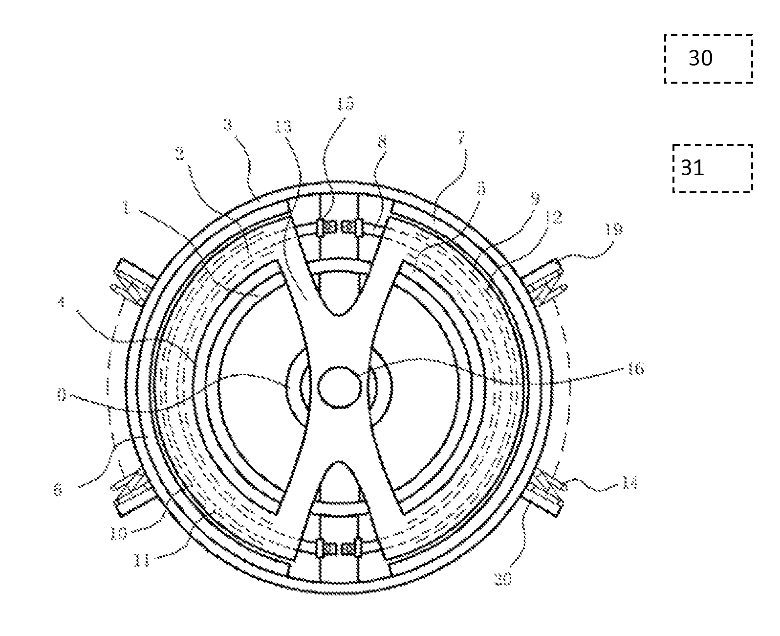
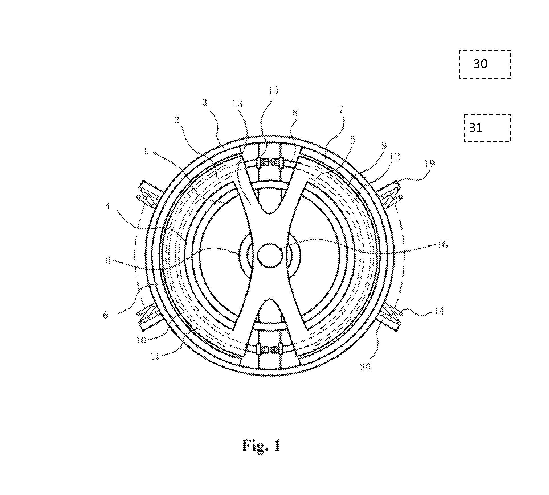
[0030]Please refer to drawings, the invention discloses an active electric torsional vibration damper which mainly comprising a relative rotating device I and a stationary device II.

[0031]Said relative rotating device I and stationary device II are connected by a pair of springs 14, which results in a relative elastic rotation. The springs 14 are screw springs, which are not limited but typical. The relative rotating device I comprises a cored-ring 0, inner-ring 1, middle-ring 2, outer-ring 3, and ringed Neodymium Iron Boron magnets (NdFeB magnet) 4, 5, 6, 7. The cored-ring 0, the inner-ring 1, the middle-ring 2, the outer-ring 3 are fixed together by a pair of spoke bars 8 having an included angle of 180°.

[0032]In one embodiment the magnetic-field producing elements are ringed NdFeB magnets 4, 5, 6, 7 which belong to permanent magnet, in other embodiments the magnetic field can be created by electromagnetic induction, such as utilizing conducting coil to create magnetic field, etc....


PUM

PropertyMeasurementUnit
operating temperatureaaaaaaaaaa
included angleaaaaaaaaaa
magnetic fieldaaaaaaaaaa

Abstract

The present invention provides an active electric torsional vibration damper and a method to realize the same. The invention relates to the field of vibration reduction technology for rotating machinery. The damper comprises a fixed module, a relative rotating module, conducting coils, magnetic-field producing elements. The present invention can be used to produce transient anti-torsion which is same in frequency, opposite in direction and corresponding in amplitude to achieve the effect of eliminating torsional vibration on the original shaft system. The damper realizes a prominent effect of eliminating torsional vibration without complex measures.

Description

CROSS REFERENCE TO RELATED PATENT APPLICATION[0001]The present application is the US national stage of PCT / CN2010 / 070529 filed on Feb. 5, 2010, which claims the priority of the Chinese patent application No. 200910050522.1 filed on May 2, 2009, which application is incorporated herein by reference.FIELD OF THE INVENTION[0002]The present invention relates to the field of vibration reduction technology for rotating machinery.BACKGROUND OF THE INVENTION[0003]Torsional vibration is caused by periodic fluctuation generated by the torsion loads about its average value, commonly exists in devices of rotating machinery. Generally, the torsion and the vibration thereof have complex periodic characteristics which include the vibration from a series of frequency components such as cars, combustion engines on ships, drive systems of propeller shafts, and bump mechanisms, etc. If some frequency components of dynamic load tend to equal with the natural torsional frequency of a structure, the mech...

Claims


Application Information

Patent Timeline
Patent Type & Authority Patents(United States)
IPC IPC(8): F16F15/03
CPCF16F15/18Y10T29/49002Y10T74/2127
Inventor LUO, QING
Owner LUO QING
Why Eureka
Try Eureka