Vehicle-body structure of vehicle and manufacturing method of the same

a vehicle and body technology, applied in the direction of roofs, transportation and packaging, vehicle arrangements, etc., can solve the problems that vibrations occurring at various parts of the vehicle cannot be effectively restrained from transmitting to the inside of the vehicle compartment, and achieve the effect of reducing vehicle noise, ensuring safety, and ensuring safety

Active Publication Date: 2014-04-29
MAZDA MOTOR CORP
View PDF14 Cites 14 Cited by
  • Summary
  • Abstract
  • Description
  • Claims
  • Application Information

AI Technical Summary

Benefits of technology

[0006]An object of the present invention is to provide a vehicle-body structure of a vehicle or a manufacturing method of the same which can properly restrain the vibration transmission, thereby improve the comfortable ride and reduce the noises of the vehicle, ensuring the sufficient rigidity of the vehicle-body structure.
[0008]According to the present invention, since the reinforcing member is provided in the closed-section portion formed by a single vehicle-body forming member made in a hollow-tube shape, or plural vehicle-body forming members joined together, for example, the rigidity of the vehicle-body forming member(s) and a portion of the vehicle body formed by the vehicle-body forming member(s) can be improved, so that any deformation of that portion, collapse of the closed-section portion, or the like can be properly restrained. In this case, since the joint portion of the vehicle-body forming member and the reinforcing member includes the rigid joint portion by using welding, bolt fastening or the like as well as the flexible joint portion by using the damping member, the vehicle-body forming member and the reinforcing member can be joined together firmly with the rigid joint portion, thereby improving the rigidity, and vibrations of the vehicle-body forming member(s) can be properly reduced by the damping member provided at the flexible joint portion. Thereby, the above-described vibration transmission can be properly restrained, ensuring the sufficient rigidity of the vehicle-body structure, so that the comfortable ride can be properly improved and the noises can be properly reduced. Herein, the present invention may not require any additional members to restrain the vibration transmission, so that the above-described effects can be advantageously provided, avoiding any improper weight increase of the vehicle body or the like. Further, since the joint portion of the vehicle-body forming member(s) and the reinforcing member is provided at or in the vicinity of the dent portion of the vehicle-body forming member(s) which dents toward the inside of the closed-section portion, it can be effectively restrained that the deformation or collapse of the closed-section portion start from the dent portion of the closed-section portion where a stress concentration may occur easily, and also the vibrations of the vehicle-body forming member(s) can be effectively reduced at the dent portion of the closed-section portion where a strain-energy concentration may occur easily.
[0009]According to an embodiment of the present invention, another vehicle-body forming member which is different from the at least one vehicle-body forming member is joined to an outer face of the dent portion. Thereby, the vibrations transmitted between the vehicle-body forming member(s) forming the closed-section portion and the other vehicle-body forming member can be effectively reduced, thereby providing the above-described effect more effectively.
[0012]According to another embodiment of the present invention, the rigid joint portion and the flexible joint portion are provided at one flange portion of the bulkhead. Thereby, the joint strength of the bulkhead to the vehicle-body forming member can be ensured and the vibration-damping effect can be provided by the joint portion of the flange portion
[0014]According to anther aspect of the present invention, there is provided a manufacturing method of a vehicle-body structure of a vehicle which comprises at least one vehicle-body forming member forming a closed-section portion and having a dent portion which dents toward an inside of the closed-section portion and a reinforcing member provided in the closed-section portion of the vehicle-body forming member and joined to the vehicle-body forming member, the method comprising a step of joining the vehicle-body forming member and the reinforcing member at a position which is located at or in the vicinity of the dent portion of the vehicle-body forming member, wherein the joining step includes a rigid joining step of joining the vehicle-body forming member and the reinforcing member with a direct contact thereof and a flexible joining step of joining the vehicle-body forming member and the reinforcing member via a damping member provided therebetween. A vehicle-body structure of a vehicle manufactured by this method can provide the same effects described above for the present invention.

Problems solved by technology

According to the structures disclosed in the above-described patent publications, however, there is a concern that while improvement of the rigidity is achieved, vibrations occurring at various portions of the vehicle may not be effectively restrained from transmitting to the inside of the vehicle compartment in some cases depending on arrangement positions, shapes, and the like.

Method used


Image

  • Vehicle-body structure of vehicle and manufacturing method of the same
  • Vehicle-body structure of vehicle and manufacturing method of the same
  • Vehicle-body structure of vehicle and manufacturing method of the same

Examples


first embodiment

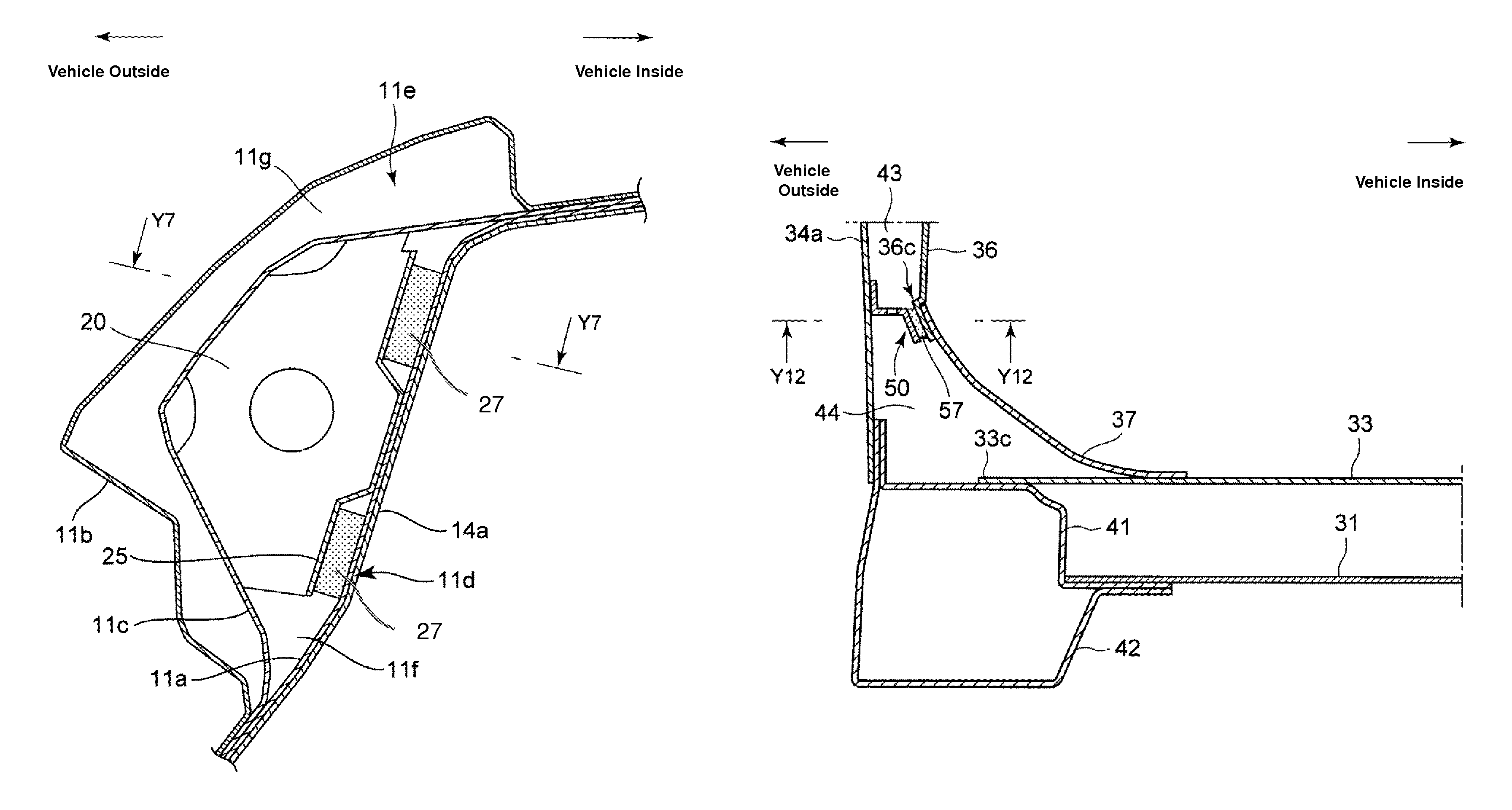
[0051]FIG. 8 is a perspective view showing the bulkhead as the reinforcing member according to the present invention. FIG. 8 shows a state in which a damping member is attached to the bulkhead. The bulkhead 20 comprises, as shown in FIG. 8, a partition face portion 21 which partitions the closed-section portion 11f, a first flange portion 32 which is provided at an upper side portion of the partition face portion 21 and extends rearward, second and third flange portions 23, 24 which are provided at a vehicle-outside side portion of the partition face portion 21 and extend rearward, and a fourth flange portion 25 which is provided at a vehicle-inside side portion of the partition face portion 21 and extends forward. A seat portion 25a is formed at the fourth flange portion 25 in a recess shape so as to accommodate viscoelastic members 27 therein, which will be described. Herein, a hole portion 26 is formed at the partition face portion 21 for weight reduction.

[0052]The first, second ...

second embodiment

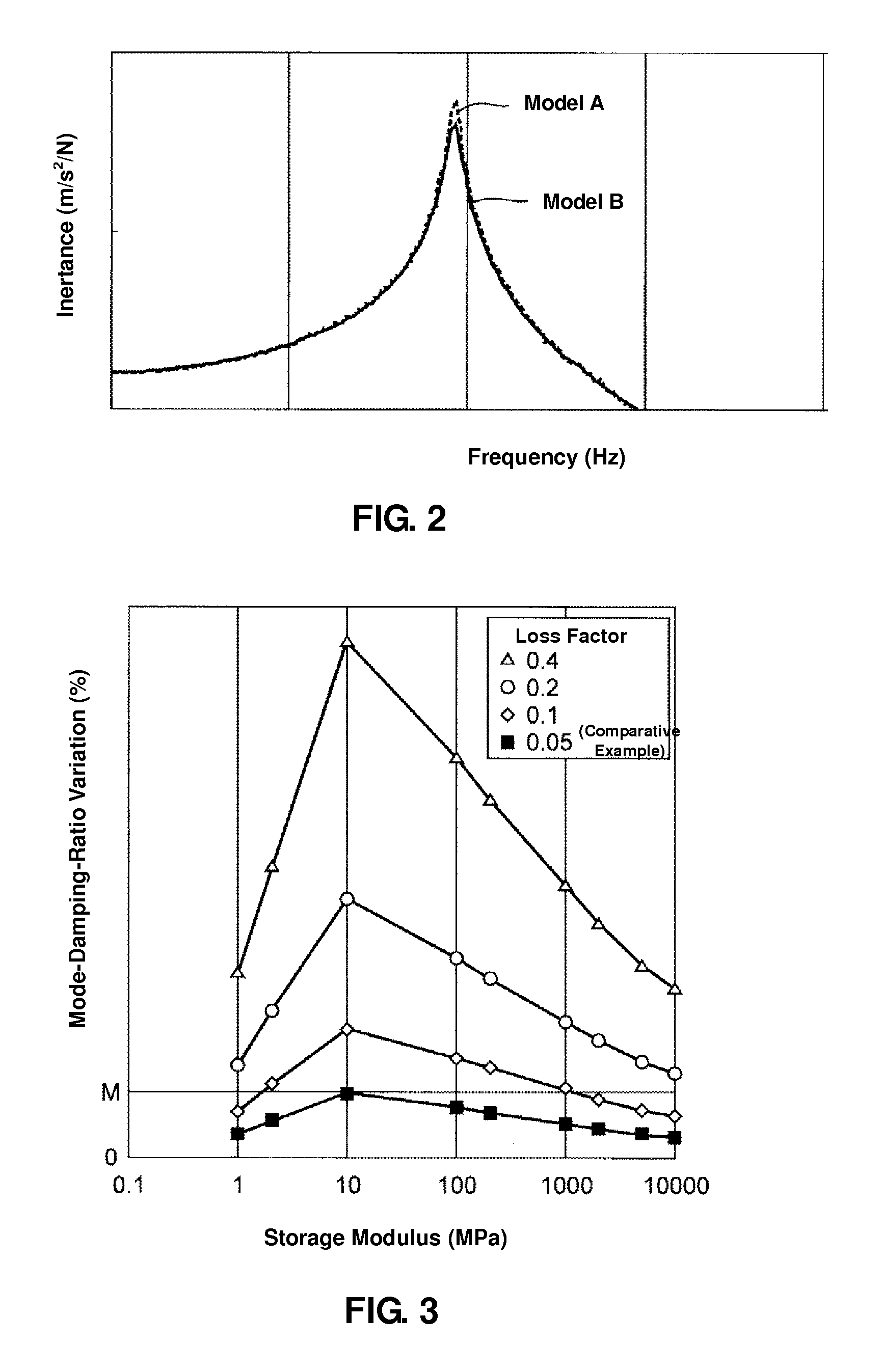
[0054]Herein, the viscoelastic member 27 having the physical properties which fall within the range enclosed by six coordinate points: (1, 0.4), (1, 0.2), (2, 0.1), (1000, 0.1), (10000, 0.2) and (10000, 0.4) in the X-Y coordinate system with X axis of the storage modulus and Y axis of the loss factor, or the range exceeding the loss factor of 0.4 may be preferably used. A viscoelastic member similar to the above-described viscoelastic member 27 may be preferably used in a second embodiment which will be described below.

[0055]While the hollow frame formed by the roof rail inner 11a and the roof rail reinforcement 11c and the bulkhead 20 are joined together at the dent portion 11d denting toward the inside of the closed-section portion of the roof rail inner 11a in the present embodiment, they may be joined together at a position which is located in the vicinity of the dent portion 11d.

[0056]Further, while the bulkhead 20 is joined in the closed-section portion 11f formed by the roof...


PUM

PropertyMeasurementUnit
storage modulusaaaaaaaaaa
flexibleaaaaaaaaaa

Abstract

In a vehicle-body structure of a vehicle which comprises vehicle-body forming members forming a closed-section portion and having a dent portion which dents toward an inside of the closed-section portion, and a reinforcing member provided in the closed-section portion and joined to the vehicle-body forming members, a joint portion of the vehicle-body forming members and the reinforcing member includes a rigid joint portion where the vehicle-body forming members and the reinforcing member are joined with a direct contact thereof and a flexible joint portion where the vehicle-body forming members and the reinforcing member are joined via a damping member provided therebetween, and this joint portion is provided at or in the vicinity of the dent portion.

Description

BACKGROUND OF THE INVENTION[0001]The present invention relates to a vehicle-body structure of a vehicle and a manufacturing method of the same.[0002]Vehicles, such as automotive vehicles, are required to increase the rigidity of a vehicle body in order to improve the comfortable ride and the safety. Japanese Utility Model Laid-Open publication Nos. 59-182472 and 60-097673, for example, disclose structures for increasing the rigidity of the vehicle body in which a reinforcing member is provided in a closed-section portion formed by a vehicle-body forming member.[0003]The first one of the above-described patent publications discloses the structure in which the bulkhead is arranged in a bamboo-joint shape in the closed-section portion of the side sill formed by the side sill outer and the side sill inner, and the flanges formed at its periphery are joined to the inner faces of the side sill outer and the side sill inner by both spot welding and an adhesive agent.[0004]The second one of...

Claims


Application Information

Patent Timeline
Patent Type & Authority Patents(United States)
IPC IPC(8): B62D25/20B62D25/02
CPCB62D25/02B62D25/2027B62D25/088Y10T29/49622
Inventor KUROGI, OSAMUSUGIHARA, TSUYOSHINAKAGAWA, KOHYANAGAO, KUNIAKITERADA, SAKAYUKOWAKI, MIHOIYOSHI, AKIRAWATANABE, SHIGEAKI
Owner MAZDA MOTOR CORP
Why Eureka
Try Eureka