X-ray imaging

a technology of x-ray imaging and x-ray light, applied in the field of x-ray imaging, can solve the problems of false detection of contaminants, inability to set a suitable threshold level, and waste of bags containing contaminants, so as to increase the speed at which the apparatus may check a product, reduce the number of pixels unnecessarily compared to their neighbours, and increase the chances of finding contaminants

Active Publication Date: 2014-04-29
ILLINOIS TOOL WORKS INC
View PDF12 Cites 0 Cited by
  • Summary
  • Abstract
  • Description
  • Claims
  • Application Information

AI Technical Summary

Benefits of technology

[0014]By identifying suspect pixels on the basis of a predetermined value, the number of pixels unnecessarily compared to their neighbours is reduced, which increases the speed at which the apparatus may check a product for contaminants. The predetermined value may be set in accordance with the product being checked or the contaminants to be detected, where it is known that pixels having a grey value above the predetermined value cannot be contaminants. Preferably, a high predetermined value is selected, since this increases the chances of finding contaminants in lighter parts of the image. For very large images, the calculation for all pixels in the image may take more than 100 ms and it may be practical to use a lower threshold value in order to speed the calculation up.

Problems solved by technology

This technique may be adequate when the product is homogeneous, however, if the product is non-homogenous and contains light and dark regions, such as a bag of randomly arranged sweets, it is impossible to set a suitable threshold level.
If the threshold level is set too high then bags not containing contaminants will trigger false alarms and have to be discarded.
This is very costly as each then has to be carefully examined to determine whether it was a true or false alarm, for if the alarm is a true alarm then the source of the foreign particle may need to be established.
This technique is more effective than the simple comparison technique, discussed above, but suffers similar drawbacks since there may be a great difference in grey values between an adjacent pixel bridging an edge of a product, resulting in false contaminant identification.
This is particularly a problem with products of uneven shape, for example the bag of sweets, where the edge of the product cannot be predicted.

Method used


Image

  • X-ray imaging
  • X-ray imaging

Examples


Embodiment Construction

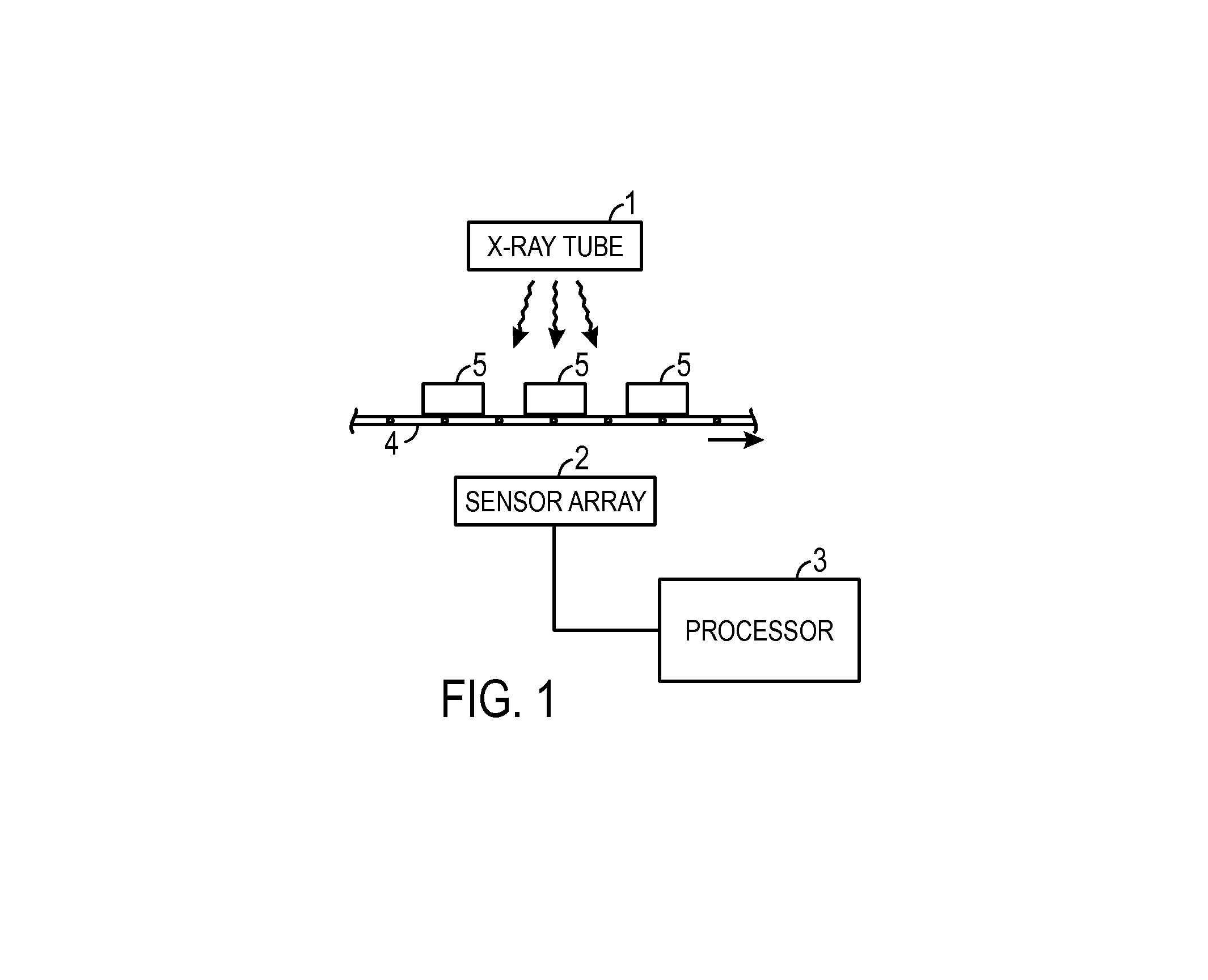
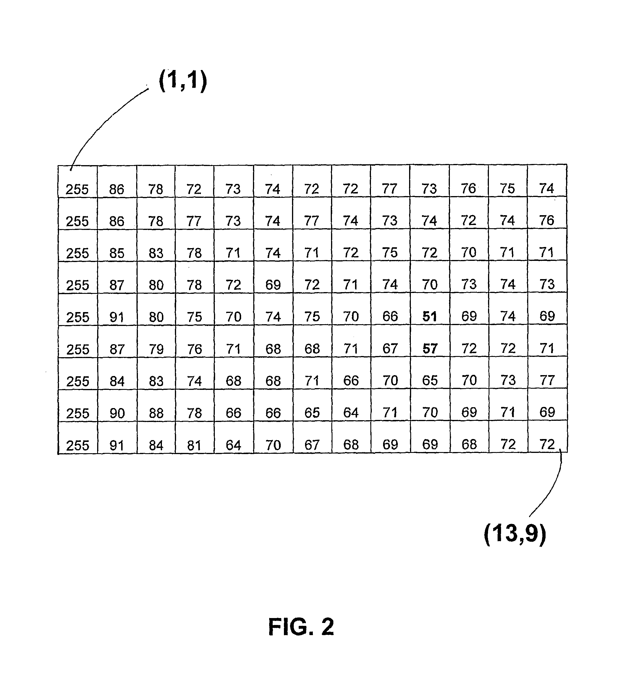
[0023]Referring to FIG. 1, there is shown an X-ray imaging apparatus according to the present invention. The apparatus comprises an X-ray tube 1, a sensor array 2 for detecting contaminants and a computer 3 for processing the sensor data. A conveyer belt 4 is provided, along which products 5 to be scanned are conveyed. In use, a high voltage is applied to the X-ray tube, which emits a stream of X-rays that are focused and reduced to a fan beam that passes through a product on the conveyer belt before entering the sensor array 2, as is well known in the art. The sensor converts the X-ray signal into an 8-bit pixilated image. Each pixel has a grey value ranging from 0 to 255, where 0 represents black and 255 represents white. The image is passed to the computer for processing. There may or may not be a screen provided for displaying the image. The computer processes the 8-bit image using the following algorithm:

X=1 to Width(BITMAP)

Y=1 to Height(BITMAP)

Suspect=value(X,Y)

UpDownMin=Minim...


PUM


Abstract

An X-ray scanning apparatus for locating a contaminant in a product, the apparatus comprising: means for generating an X-ray image of the product; means for assigning a grey scale value to a plurality of pixels; means for identifying a plurality of suspect pixels; means, which for each suspect pixel: selects two neighboring pixels in a first direction lying on opposed sides of the suspect pixel and determines which of the first direction pixels has the lowest grey value; selects two neighboring pixels in a second direction lying on opposed sides of the suspect pixel and determines which of the second direction pixels has the lowest grey value; determines a first direction difference value by taking the grey value difference between the lowest grey value first direction pixel and the grey value of the suspect; determines a second direction difference value by taking the grey value difference between the lowest grey value second direction pixel and the grey value of the suspect; determines a first direction score from the first direction difference value; determines a second direction score from the second direction difference value; compares said scores with a threshold value; and identifies the suspect pixel as representing a contaminant if said threshold value is exceeded.

Description

CROSS-REFERENCE TO RELATED APPLICATIONS[0001]This application claims priority to and the benefit of PCT Application No. PCT / IB2008 / 001190 entitled “X-Ray Imaging”, filed on May 13, 2008, which is herein incorporated by reference in its entirety, and which claims priority to and the benefit of GB Application No. GB0709183.8, entitled “X-Ray Imaging”, filed on May 14, 2007, which is herein incorporated by reference in its entirety.[0002]This invention relates to X-ray imaging. In particular, it relates to an X-ray imaging means for identifying contaminants such as foreign bodies, for example metallic particles, in products, particularly foodstuffs.BACKGROUND OF THE INVENTION[0003]Generally, X-ray imaging identifies contaminants in products by a simple comparison of all the pixels in an image of the product against some value (or “threshold”). For example, every pixel in the image is assigned a grey value and these grey values are compared to a threshold grey value, wherein any pixels ...

Claims


Application Information

Patent Timeline
Patent Type & Authority Patents(United States)
IPC IPC(8): G06K9/00
CPCG06T2207/30128G01N23/04G06T7/0004
Inventor KAINE, CHRISTOPHER JAMESDEKKER, ALAIN STEPHEN
Owner ILLINOIS TOOL WORKS INC
Why Eureka
Try Eureka