System and methods for obstacle mapping and navigation

a mapping system and obstacle technology, applied in the field of mapping environments, can solve problems such as non-uniform sampling theory, and achieve the effect of facilitating “see-through” capabilities

Inactive Publication Date: 2014-04-29
STC UNM
View PDF24 Cites 56 Cited by
  • Summary
  • Abstract
  • Description
  • Claims
  • Application Information

AI Technical Summary

Benefits of technology

[0009]The invention maps static or dynamic objects (otherwise referred to herein as “obstacles”) in an environment. The invention determines the position of an object—occluded or non-occluded—within an environment without sensing the object directly. More specifically, the inv...

Problems solved by technology

This is accomplished by using non-uniform...

Method used


Image

  • System and methods for obstacle mapping and navigation
  • System and methods for obstacle mapping and navigation
  • System and methods for obstacle mapping and navigation

Examples


Embodiment Construction

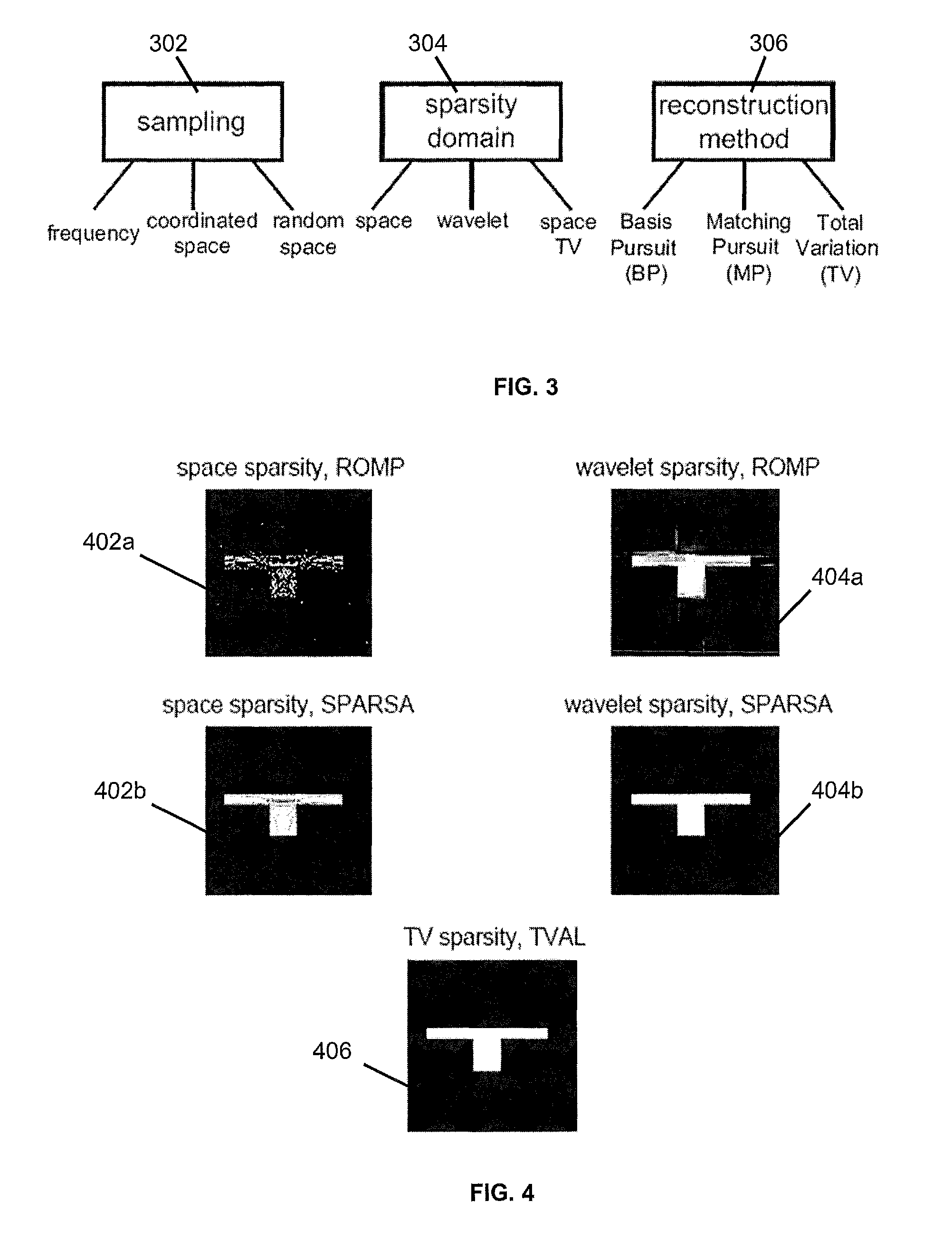
[0026]Compressive sampling (otherwise known as compressed sensing, compressive sensing or sparse sensing) asserts that certain signals can be acquired from far fewer samples or measurements than traditional methods. More specifically, compressive sampling is based on the fact that real-world signals typically have a sparse representation in a certain transformed domain. Compressive sampling relies on sparsity and incoherence. Sparsity pertains to the signals of interest and incoherence pertains to the sensing modality.

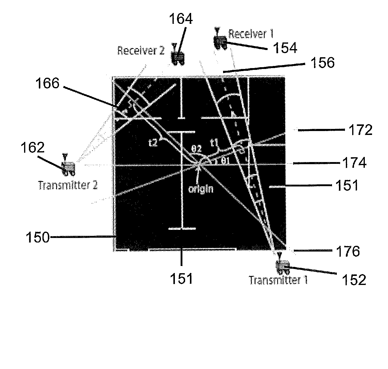
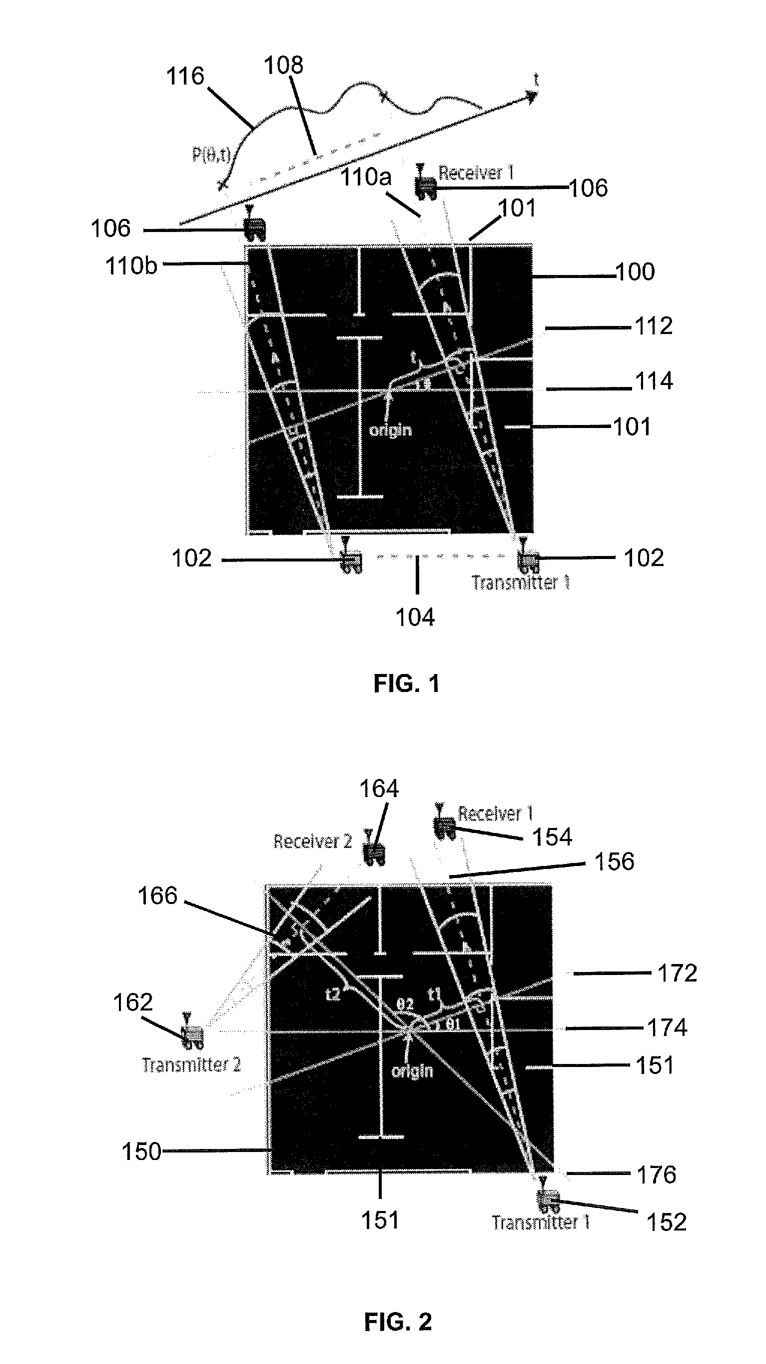
[0027]In an overview of compressive sampling, consider the case where a vector xεN is to be recovered. For two-dimensional (“2D”) signals, vector x can represent the columns of the matrix of interest stacked up to form a vector. The incomplete linear measurement of vector x obtained by the robot devices, wherein KK. Thus, γ=Φr where Φ is the observation matrix. Clearly solving for x based on the observation set γ is an ill-posed problem as the system is severely under-...


PUM


Abstract

A system and methods for building a map non-invasively (i.e. mapping of occluded and non-occluded obstacles) based on a small number of wireless channel measurements. Approaches for building an obstacle map are based on coordinated space, random space and frequency sampling, such that the sparse representation of the map in space, wavelet or spatial variations, are exploited in order to build the map with minimal sensing.

Description

[0001]This application claims the benefit of U.S. Provisional Patent Application No. 61 / 456,003 filed Oct. 29, 2010.STATEMENT CONCERNING FEDERALLY SPONSORED RESEARCH[0002]The invention was made with government support under grant 0846483 awarded by the National Science Foundation. The United States Government has certain rights in the invention.FIELD OF THE INVENTION[0003]The invention relates generally to mapping environments including obstacles positioned within those environments. More particularly, the invention relates to a system and methods for determining the position of obstacles within an environment without sensing the obstacles directly.BACKGROUND OF THE INVENTION[0004]Obstacle mapping is crucial to the robust operation of robotic networks. Specifically, obstacle mapping relates to determining the location of an object within an environment. In existing approaches, only the obstacles that are directly visible to the robot can be mapped. In other words, occluded obstacles...

Claims


Application Information

Patent Timeline
IPC IPC(8): G01S13/34G05D1/02G09B29/00
CPCG01S13/003G01S13/89G09B29/00G01S13/34G05D1/02G05D1/0274G05D1/0291G05D2201/0207
Inventor MOSTOFI, YASAMINSEN, PRADEEP
Owner STC UNM
Why Eureka
Try Eureka