Superfinishing machine and method

Inactive Publication Date: 2007-01-11
SUPFINA MACHINE
View PDF67 Cites 8 Cited by
  • Summary
  • Abstract
  • Description
  • Claims
  • Application Information

AI Technical Summary

Benefits of technology

[0027] According to the third embodiment, a single machine may be placed within multiple workflows, without a change in setup. A multiposition turret is provided, which is preferably associated with one or more automated feeds and/or removal mechanism to insert the superfinishing machine into an automated flow. Typically, a superfinishing machine is set up for a single type of workpiece, which is inserted and extracted from the chuck in its normal operating position. According to the present embodiment, a plurality of chucks are provided on a turret, which is automatically controlled. Each chuck can be adapted for a different workpiece, so, without a change in setup, the machine can operate on different workpieces with different superfinishing processes, simply by calling a superfin

Problems solved by technology

The turret may be fluid filled, and include hydraulic elements, so that a change in orientation from a downward tool direction may result in difficulties in operation.
Likewise, the turret, though typically designed t

Method used


Image

  • Superfinishing machine and method
  • Superfinishing machine and method
  • Superfinishing machine and method

Examples


first embodiment

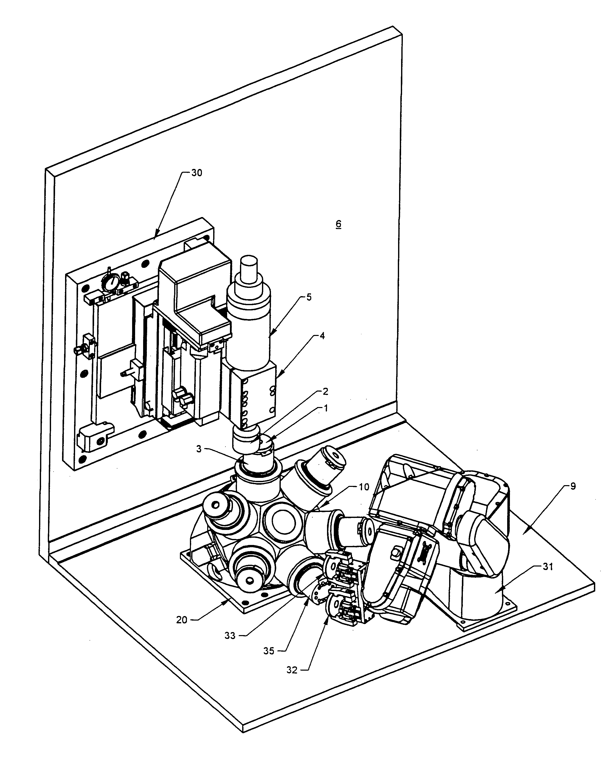
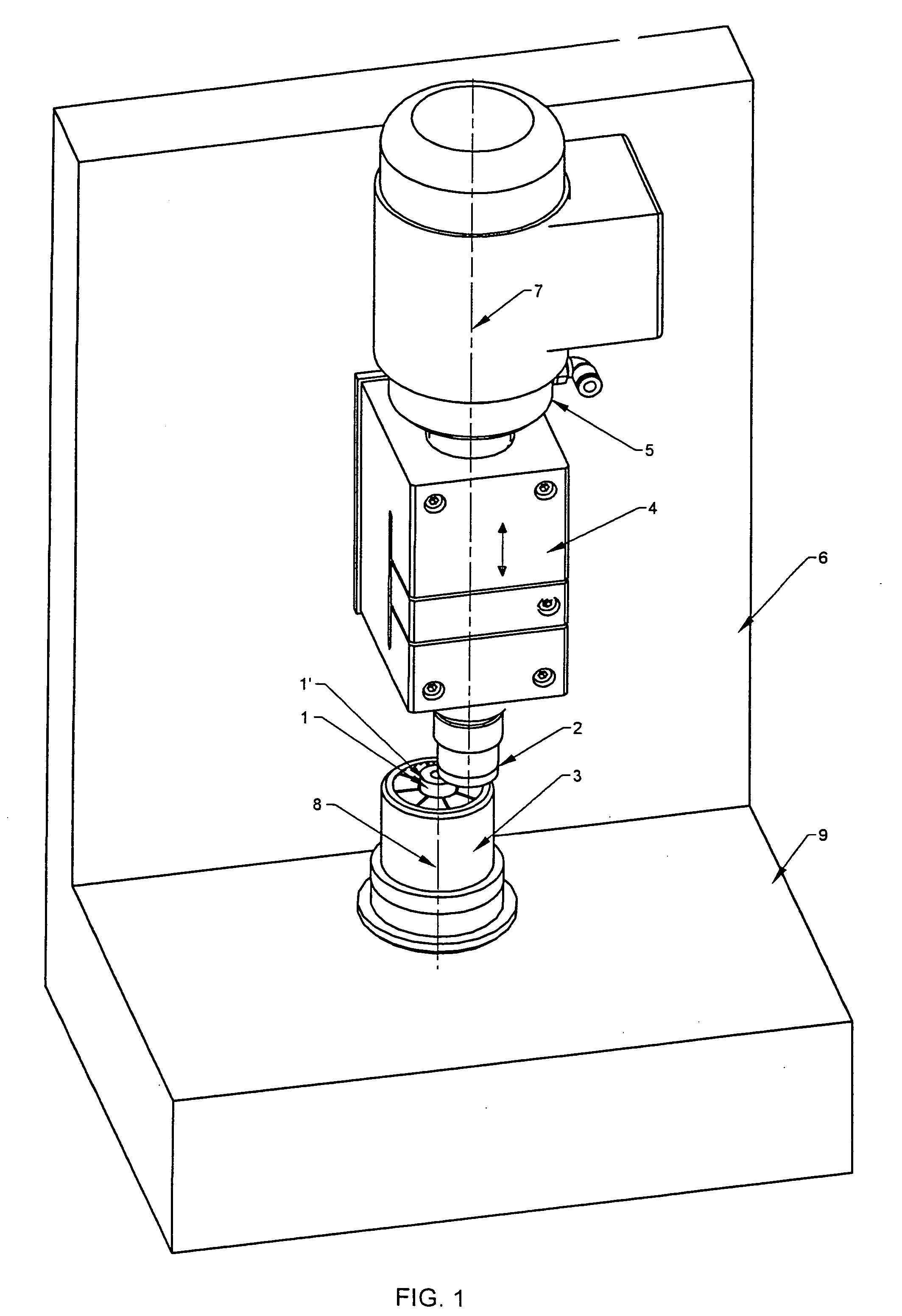
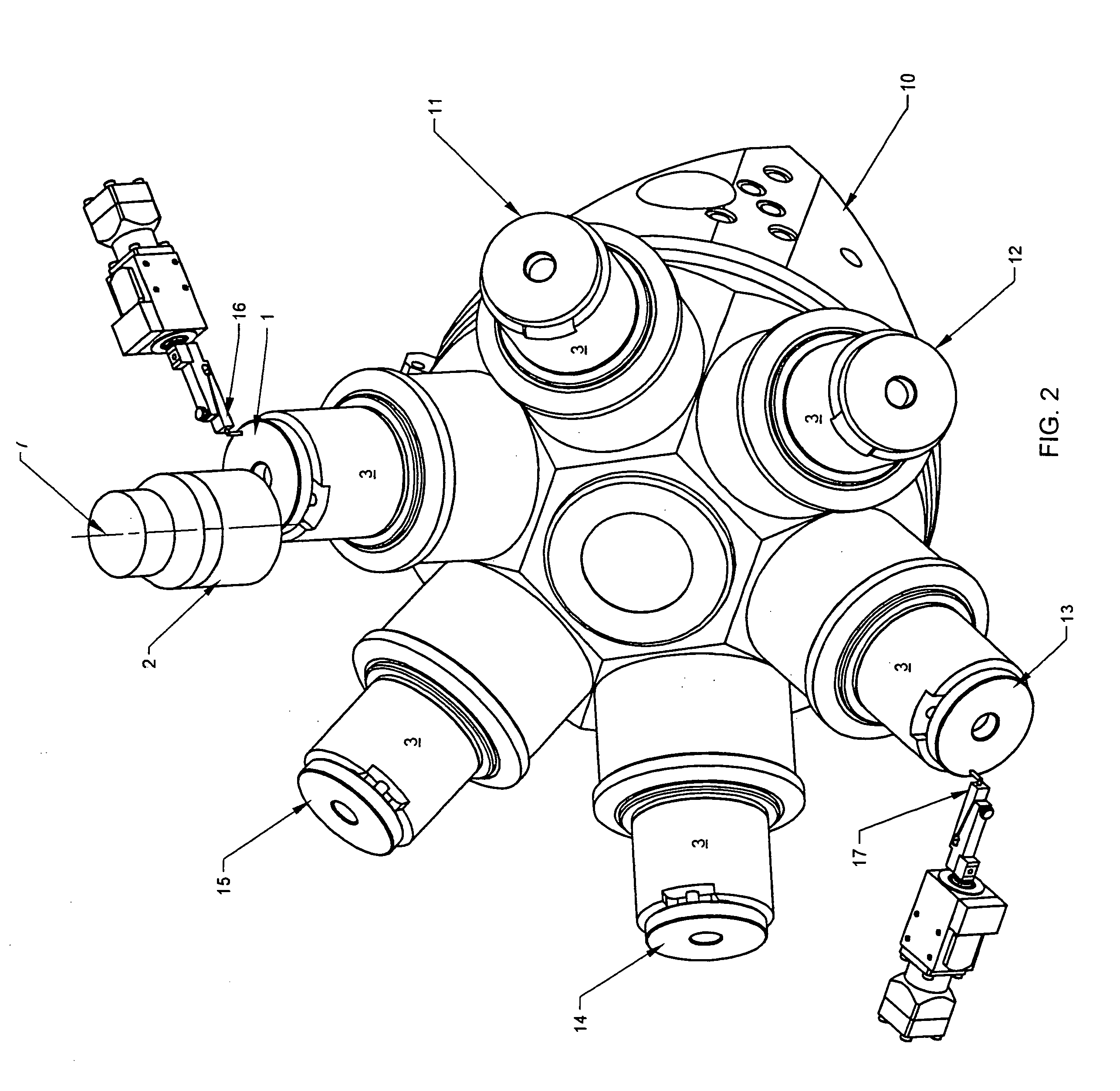
[0048]FIG. 2 shows a superfinishing apparatus having a set of chucks 3 mounted on respective spindles of a turret 10. In this arrangement, the superfinishing operation can proceed simultaneously with loading and unloading, and / or a gauging process may be conducted prior to, during an intermediate step, or after the process, by a gauge 17 located in conjunction with a workpiece 13 in a non-machining chuck, without unduly reducing process throughput. Of course, gauging may also be conducted in-process by a gauge 16 located in conjunction with a workpiece 1 in a machining chuck. Thus, the superfinishing process may proceed while secondary operations are performed at different turret stations.

[0049] The preferred turret is a Pibomulti 256, 356, or 358, which provides a single electrical servomotor to both position the turret and drive the spindle in at single turret location. The turret 10 permits loading and unloading through a hydraulically clamp at a single position.

[0050] As shown...

second embodiment

[0057]FIG. 5 shows a second embodiment of the invention in which multiple turret 10 locations correspond to different processing operations, allowing the superfinishing machine to perform a plurality of different processing operations on different workflows without additional changeover.

[0058] This embodiment is structurally similar to the first embodiment shown in FIG. 2, except perhaps that multiple flows of workpieces 41, 42, 43, 44, 45, 46 may interact with the turret 10, to load and unload the respective chucks. However, from a control standpoint, this embodiment is somewhat different.

[0059] In prior systems, control complexity was limited by providing a system which was set up and run to perform a single operation. The cup wheel 2 and workpiece 1 each rotated about a defined axis, and the control used its process parameter sensor or a position sensor to initiate contact. Thereafter, the process was controlled to produce a finish on the workpiece with the desired parameters, ...

third embodiment

[0063]FIGS. 6A, 6B and 6C show a third embodiment of the invention in which a single workpiece 1 is processed on different surfaces 1′, 1″ with respectively different processing parameters while mounted in the same chuck 3. In this case, the control employs respectively different control parameters, if for nothing else, to define the offsets A, B of the various surfaces to be treated, but likely also in-process conditions as well. Accordingly, during processing, the control causes the cup wheel 2 to contact a first surface 1′ and applies a respective treatment, until completed. After the first surface 1′ is treated, a second processing program is triggered which then realigns the axes 7, 8 of the cup wheel 2 and workpiece 1. In some instances, the cup wheel 2 is replaced with a different abrasive, appropriate for the subsequent operation. Using the next set of processing parameters, the subsequent surface 1″ is treated. These sequential operations, calling sequential sets of control...


PUM

PropertyMeasurementUnit
Depthaaaaaaaaaa
Heightaaaaaaaaaa

Abstract

A superfinishing system and method, wherein an abrasive is employed to process a workpiece, and wherein the system simultaneously mounts a plurality of workpieces in a diagonal turret, or mounts a plurality of different types of workpieces in a plurality of chucks for different operations thereon, or performs a plurality of different operations on the same workpiece without remounting. The system improves throughput by allowing flexibility in the operation and multitasking.

Description

BACKGROUND OF THE INVENTION [0001] 1. Field of the Invention [0002] This invention relates to high throughput cup wheel superfinishing systems and methods therefore, in particular relating to workpiece identification, loading, unloading and repositioning. [0003] 2. Description of the Prior Art [0004] Superfinishing is a well known process in which an outer surface of a workpiece is removed, using a process which generates little heat or surface stress, to produce a smooth surface having a precise contour and properties similar to the bulk material. [0005] A superfinishing operation can be performed on almost any previously machined surface which may have a flat, cylindrical, spherical or other specific configuration. It improves the finish of the previously machined surface by removing surface material or “smear metal” left by the previous machining operation, and by cutting off ridges on the base metal surface of the workpiece. Superfinishing can also effect small corrections in th...

Claims


Application Information

Patent Timeline
IPC IPC(8): B24B51/00B24B5/00
CPCB24B35/00
Inventor KLOTZ, NORBERT
Owner SUPFINA MACHINE
Why Eureka
Try Eureka