Animatronic eye with an electromagnetic drive and fluid suspension and with video capability

a technology of electromagnetic drive and fluid suspension, applied in the field of simulating apparatus, to achieve the effect of easing the installation

Active Publication Date: 2014-05-06
DISNEY ENTERPRISES INC
View PDF8 Cites 12 Cited by
  • Summary
  • Abstract
  • Description
  • Claims
  • Application Information

AI Technical Summary

Benefits of technology

[0011]The eye assembly may utilize an electromagnetic drive in some embodiments, and, to this end, the inner clear sphere may have four permanent magnets or magnetic elements mounted to its top, bottom, and two sides at antipodal points about the equator or a great circle of the sphere. On the outer shell, four electromagnetic drives may be mounted so as to be associated with each of these inner sphere magnets (e.g., each electromagnetic drive is used to apply a magnetic or driving force upon one of the inner sphere magnets). The external drives may each includes a pair of electromagnetic coils in which the coils are positioned adjacent and proximate to each other but, in some cases, on opposite sides of the equator (or a great circle of the outer shell that generally bisects the outer shell into a front and back shell portion or hemisphere) and with each drive equidistally spaced about the equator such that the four drives are located at 90 degree spacings and such that opposite electromagnetic drives include antipodal coils (e.g., coils on opposite sides of the outer shell with their center points being antipodal points on the outer shell / spherical housing). The external drive coils may be lay-flay, magnetic coils that may be selectively operated to generate magnetic fields (e.g., energize or drive antipodal coils concurrently) to yaw and tilt / pitch the inner sphere or eyeball. The design of the eye assembly has no external moving parts, which eases its installation in new and retrofit, animatronic applications.
[0016]In some embodiments, the solid body and the wall of the outer shell may be formed of a substantially transparent plastic such as an acrylic. In practice, the suspension liquid may be chosen to have a specific gravity such that the inner sphere has neutral buoyancy whereby it floats in the center of the void space and liquid fills the space between the solid body and the inner surfaces of the outer shell wall (e.g., the body is maintained at a spaced apart distance from the shell). For example, when the body is a plastic (and may contain further weight-adding components such as permanent magnets), the liquid may be a mixture of glycerin and water such as ¾ glycerin and ¼ water or the like to achieve a desired buoyancy of the body and also, in some cases, to provide a desired viscosity so as to dampen movement of the body during quick rotation (e.g., to control movements solely on momentum or the like). In some cases, it is desirable that the inner sphere body has a diameter that is smaller than the thin wall's inner diameter but with not excessive spacing such as by providing the body with an outer diameter that is at least 80 to 90 percent or more of the inner diameter of the shell (or such that a spacing is less than about 0.5 inches and more typically less than about 0.25 inches such as less than about 0.1 inches or the like).

Problems solved by technology

The eye assembly is attractive for use as a prosthetic due to its form factor and lack of rotation of the outer shell within the recipient's eye socket (which may be undesirable due to discomfort and other issues associated with implanting prosthetics).

Method used


Image

  • Animatronic eye with an electromagnetic drive and fluid suspension and with video capability
  • Animatronic eye with an electromagnetic drive and fluid suspension and with video capability
  • Animatronic eye with an electromagnetic drive and fluid suspension and with video capability

Examples


Embodiment Construction

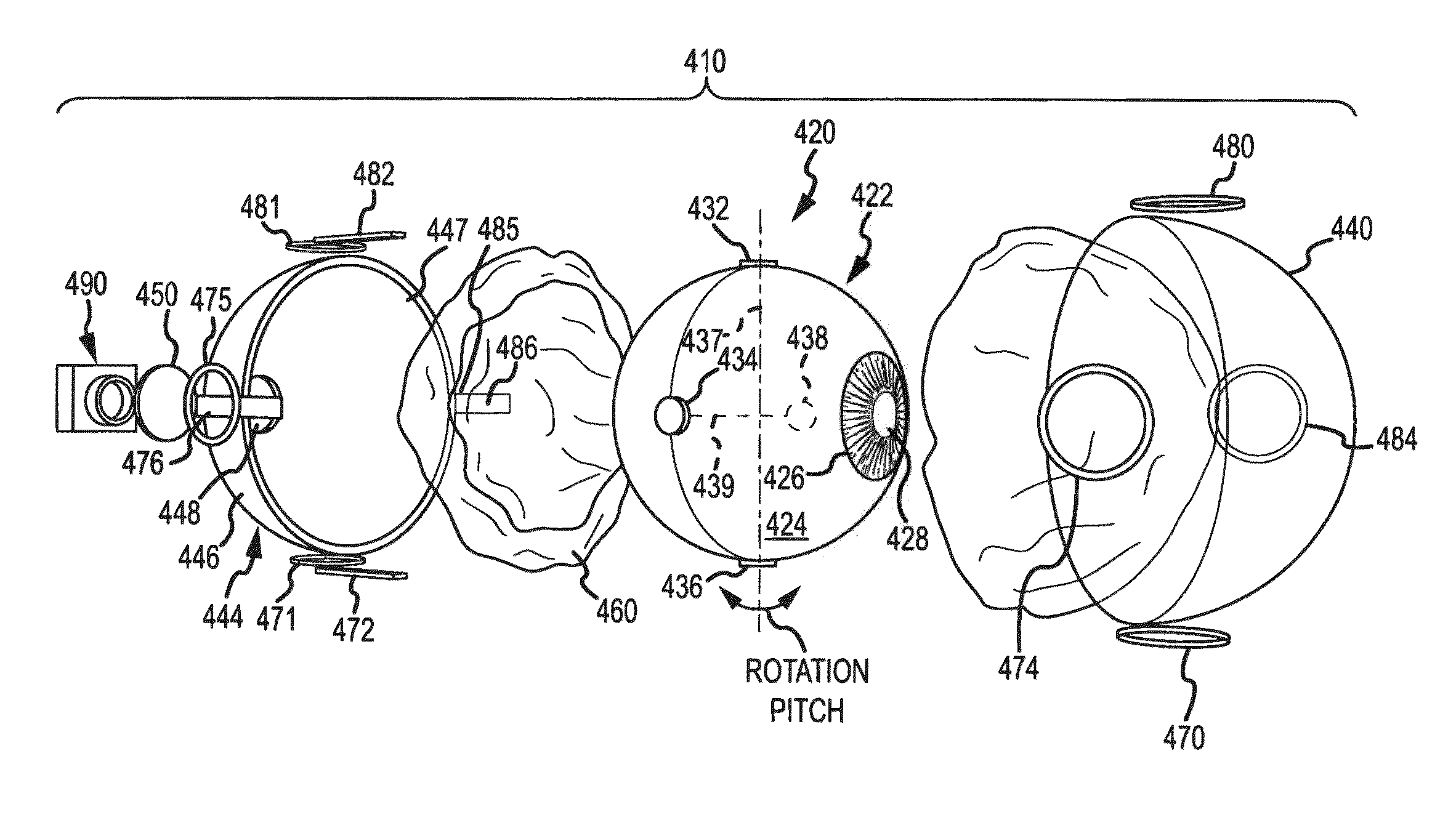
[0025]Briefly, embodiments described herein are directed to a compact, fluid-suspension, electromagnetically-gimbaled (or driven) eye that may be used in eye assemblies for animatronic figures as well as for human prosthetics. Each eye or eye assembly features extremely low operating power, a range of motion and saccade speeds that may exceed that of the human eye while providing an absence of frictional wear points (e.g., between the eyeball or inner sphere and an eye socket). The design of the eye assembly has no external moving parts, which eases its installation in new and retrofit animatronic applications.

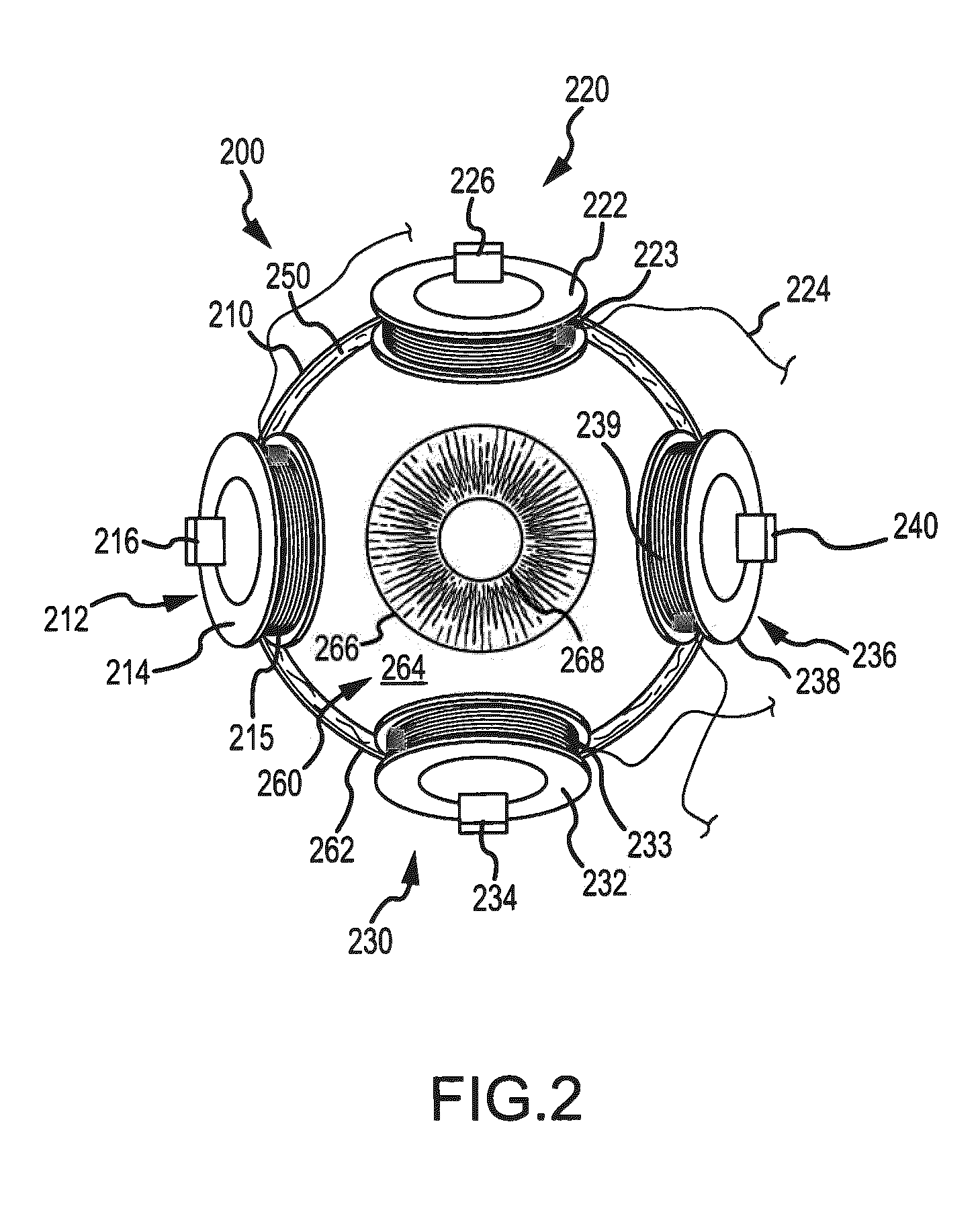
[0026]The eye assembly may include a clear or substantially transparent outer shell that contains a suspension fluid and an inner orb or sphere (e.g., an eyeball). The inner sphere may be a solid plastic or similar material ball with a set of magnetic elements attached or embedded thereon. An electromagnetic drive assembly may be provided that includes a set of magnetic drive ...


PUM


Abstract

An animatronic eye with fluid suspension, electromagnetic drive, and video capability. The eye assembly includes a spherical, hollow outer shell that contains a suspension liquid. An inner sphere is positioned in the outer shell in the suspension liquid to be centrally floated at a distance away from the shell wall. The inner sphere includes painted portions providing a sclera and iris and includes an unpainted rear portion and front portion or pupil. The shell, liquid, and inner sphere are have matching indices of refraction such that interfaces between the components are not readily observed. A camera is provided adjacent a rear portion of the outer shell to receive light passing through the shell, liquid, and inner sphere. A drive assembly is provided including permanent magnets on the inner sphere that are driven by electromagnetic coils on the outer shell to provide frictionless yaw and pitch movements simulating eye movements.

Description

BACKGROUND[0001]1. Field of the Description[0002]The present description relates, in general, to apparatus for simulating a human or human-like eye such as a robot or animatronic eye or a prosthetic eye, and, more particularly, to an animatronic or prosthetic eye assembly that utilizes fluid-suspension and is electromagnetically driven and that provides optical functions such as video capability.[0003]2. Relevant Background[0004]Animatronics are used widely in the entertainment industry to bring mechanized puppets, human and human-like figures, and characters to life. Animatronics are generally thought of as the use of electronics and robotics to make inanimate objects appear to be alive. Animatronics are used in moviemaking to provide realistic and lifelike action in front of the camera as well as in other entertainment settings such as in theme parks, e.g., to provide lifelike characters in a theme ride or a show. Animatronics are often used in situations where it may be too costl...

Claims


Application Information

Patent Timeline
Patent Type & Authority Patents(United States)
IPC IPC(8): A63H3/38A63H33/26A63H3/40
CPCG09B23/30A61F2/141H04N5/2251A63H3/40B29D11/02B33Y80/00H04N23/50A63H33/26
Inventor SMOOT, LANNY STARKESBASSETT, KATHERINE MAYHAMMOND, MARCUS
Owner DISNEY ENTERPRISES INC
Why Eureka
Try Eureka