Method for burning carbonated fuels with combustion smoke filtration before compression

Active Publication Date: 2014-05-06
LAIR LIQUIDE SA POUR LETUDE & LEXPLOITATION DES PROCEDES GEORGES CLAUDE
View PDF17 Cites 2 Cited by
  • Summary
  • Abstract
  • Description
  • Claims
  • Application Information

AI Technical Summary

Benefits of technology

The patent describes a method for removing impurities from gas using a combination of filtration and packed scrubbing towers. The filtration step is carried out using a cartridge filter, which provides a large filtration area in a compact design. This filter technology reduces the pressure drop and flow-through velocity of the gas, making it easier to remove impurities. The use of packed columns downstream of filtration further enhances the purification process. The overall effect is a more efficient and effective purification of gas.

Problems solved by technology

Climate change constitutes one of the greatest environmental challenges.
Both compression wheels and interstage heat exchangers are subject to being fouled by the solid particles resulting from the combustion.
The particles may block heat exchangers and reduce their thermal capabilities.
As regards compressor wheels, these may become unbalanced by the nonuniform build-up of mass on the wheels.
This results in mechanical shaft imbalance, vibrations and potentially machine destruction.
In such a technology, the presence of solid particles results in a loss of material on the fins, especially by erosion.
The situation is therefore confronted with a dust collection problem.
However, with a flue gas dust content of 1 mg / m3 or higher, the compression operation will suffer clogging, especially in the intermediate refrigerants, requiring stoppages for frequent maintenance.
Moreover, this degrades the compression performance.
Starting from this situation, a problem that arises is how to provide a process for the combustion of carbon-containing fuels with improved flue gas treatment, especially a treatment suitable for centrifugal compressor technology.

Method used


Image

  • Method for burning carbonated fuels with combustion smoke filtration before compression
  • Method for burning carbonated fuels with combustion smoke filtration before compression
  • Method for burning carbonated fuels with combustion smoke filtration before compression

Examples


Embodiment Construction

[0058]For a further understanding of the nature and objects for the present invention, reference should be made to the detailed description, taken in conjunction with the accompanying drawings, in which like elements are given the same or analogous reference numbers and wherein:

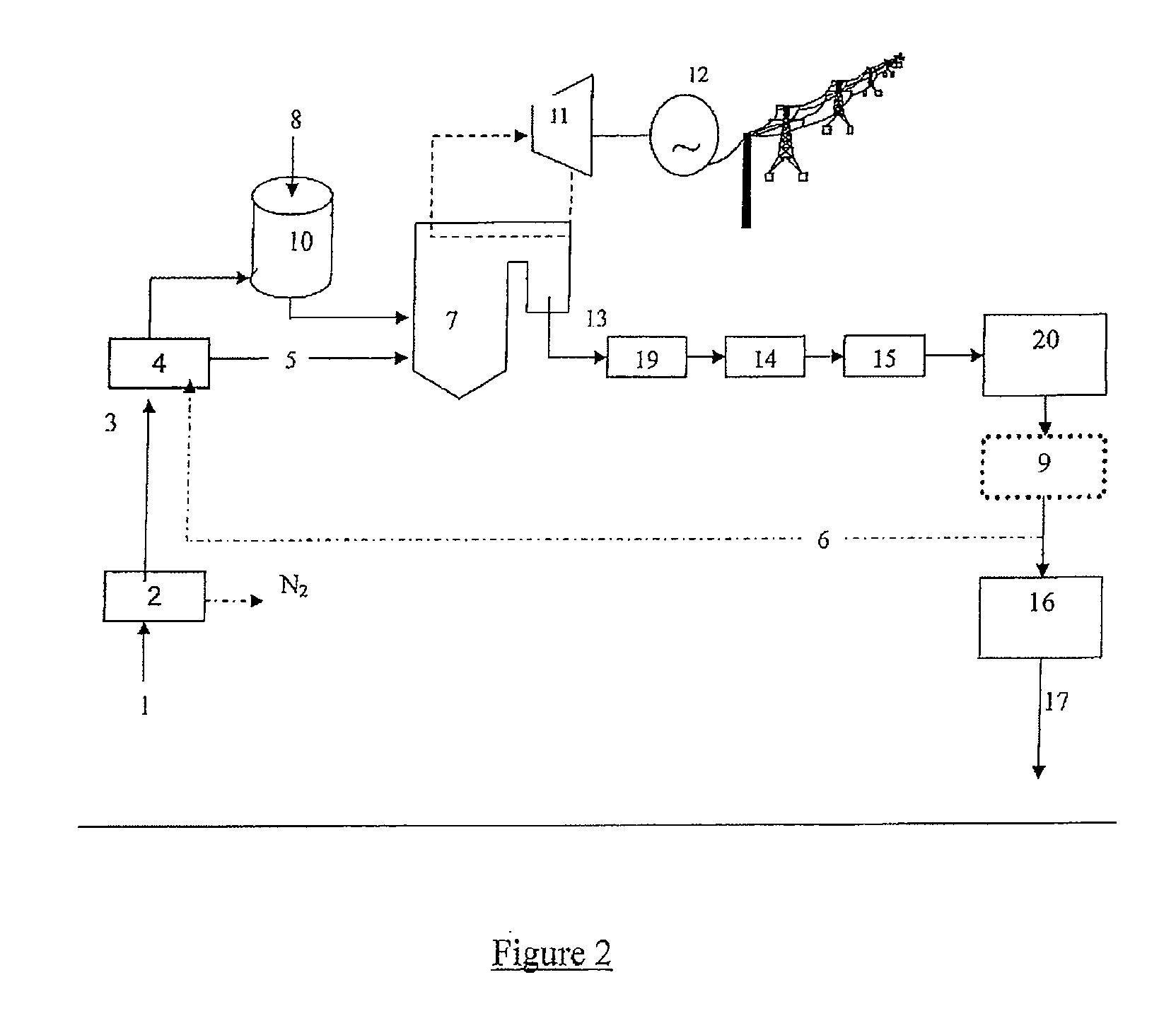
[0059]The invention will now be described in greater detail with the aid of FIGS. 1 and 2.

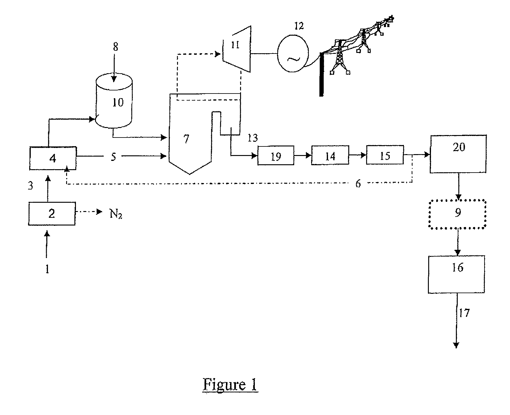
[0060]FIG. 1 illustrates a general process according to the invention, employing a pulverized-coal boiler operating with an oxidant leaner in nitrogen than air, characterized in that all of the flue gases undergo a desulfurization step.

[0061]Air 1 is fed into the air gas separation unit 2, which then produces oxygen 3. The oxygen 3 is sent to a mixer 4 where it may be mixed, via a CO2 recirculation line, with a CO2-rich recycle gas 6. The oxidant 5 coming from the mixer 4 is then fed into the pulverized-coal boiler 7, which then operates with an oxidant leaner in nitrogen than air.

[0062]The fuel 8, here raw coal, is firs...


PUM

PropertyMeasurementUnit
Temperatureaaaaaaaaaa
Concentrationaaaaaaaaaa

Abstract

A process for the combustion of a carbon-containing fuel, wherein the flue gases are filtered so as to achieve a solid particle concentration of less than 1 mg / m3 before compression, purification and sequestration or transport is presented.

Description

CROSS-REFERENCE TO RELATED APPLICATIONS[0001]This application is a §371 of International PCT Application PCT / FR2009 / 050078, filed Jan. 21, 2009, which claims priority to French Application 0850501, filed Jan. 28, 2008, the entire contents of which are incorporated herein by reference.FIELD OF THE INVENTION[0002]The present invention relates to a process for the combustion of a carbon-containing fuel, characterized in that the flue gases are filtered so as to achieve a solid particle concentration of less than 1 mg / m3 before compression, purification and sequestration or transport.BACKGROUND[0003]Climate change constitutes one of the greatest environmental challenges. The increase in carbon dioxide concentration in the atmosphere is in very large part the cause of global warming. CO2 of human origin is essentially emitted into the atmosphere through the combustion of fossil fuels in thermal power stations.[0004]Thermal power stations, by burning fuels, release heat that can be used t...

Claims


Application Information

Patent Timeline
IPC IPC(8): C01B31/20C01B32/50
CPCF23J2215/50F25J2220/82F25J2200/70F25J2210/04F25J2220/84F25J2200/02F25J2230/30F23L2900/07001F23J2219/70F25J2205/30F25J2260/80F25J2240/90B01D2257/404F25J2220/80F25J2205/66F23J2217/103F25J2230/80B01D53/77F25J2245/02F25J3/0266F25J2210/70F23J15/02B01D2257/504B01D2257/302Y02E20/322Y02C10/12F23J15/006B01D53/38F25J2205/04Y02E20/32Y02C20/40
Inventor COURT, PHILIPPEDARDE, ARTHURTRANIER, JEAN-PIERRE
Owner LAIR LIQUIDE SA POUR LETUDE & LEXPLOITATION DES PROCEDES GEORGES CLAUDE
Why Eureka
Try Eureka