Waste conveying system

a waste and conveying system technology, applied in the field of waste conveying system, can solve the problems of high cost, high cost, environmental and hygiene, and traffic, and achieve the effects of reducing disadvantages, improving profitability of tunnel construction and/or underground construction, and reducing costs

Active Publication Date: 2014-05-20
MARICAP OY
View PDF43 Cites 20 Cited by
  • Summary
  • Abstract
  • Description
  • Claims
  • Application Information

AI Technical Summary

Benefits of technology

[0008]The arrangement according to the invention has numerous significant advantages. A typically existing tunnel system, such as a traffic tunnel system, advantageously an underground tunnel system, is utilised in collecting and conveying waste, an environmentally-friendly and cost-effective waste conveying system, which also otherwise minimises disadvantages, is provided. By utilising the invention, the profitability of tunnel construction and / or underground construction can also be improved, because in addition to conventional traffic, such as passenger traffic, it is possible to convey waste according to the invention in the tunnels, most advantageously during slow traffic, such as during the night. By utilising a system according to the invention, it is also possible to improve traffic safety compared to the conventional system using waste trucks and to diminish environmental effects caused by the travelling of waste trucks, because in an area utilising the system the number of waste trucks driving above ground strongly decreases. An advantage of the system according to the invention is also that the dense social structure is typically located along the network of tunnel systems, such as underground, whereby it is as well cost-effective to handle waste management by means of the system according to the invention by utilising the ready tunnel infrastructure. Thus, the invention in an extraordinary way combines a piping conveying system of waste and a conveying path enabled by tunnels which can be also utilised in conveying waste.

Problems solved by technology

However, this causes problems for traffic, the environment and hygiene etc as waste trucks drive around on the roads picking up waste and taking it to the landfill.
This system has, however, proven to use extreme amounts of power and requires a lot of maintenance.
Conveying waste for long distances in the piping is not cost-effective in practice.

Method used


Image

  • Waste conveying system
  • Waste conveying system
  • Waste conveying system

Examples


Embodiment Construction

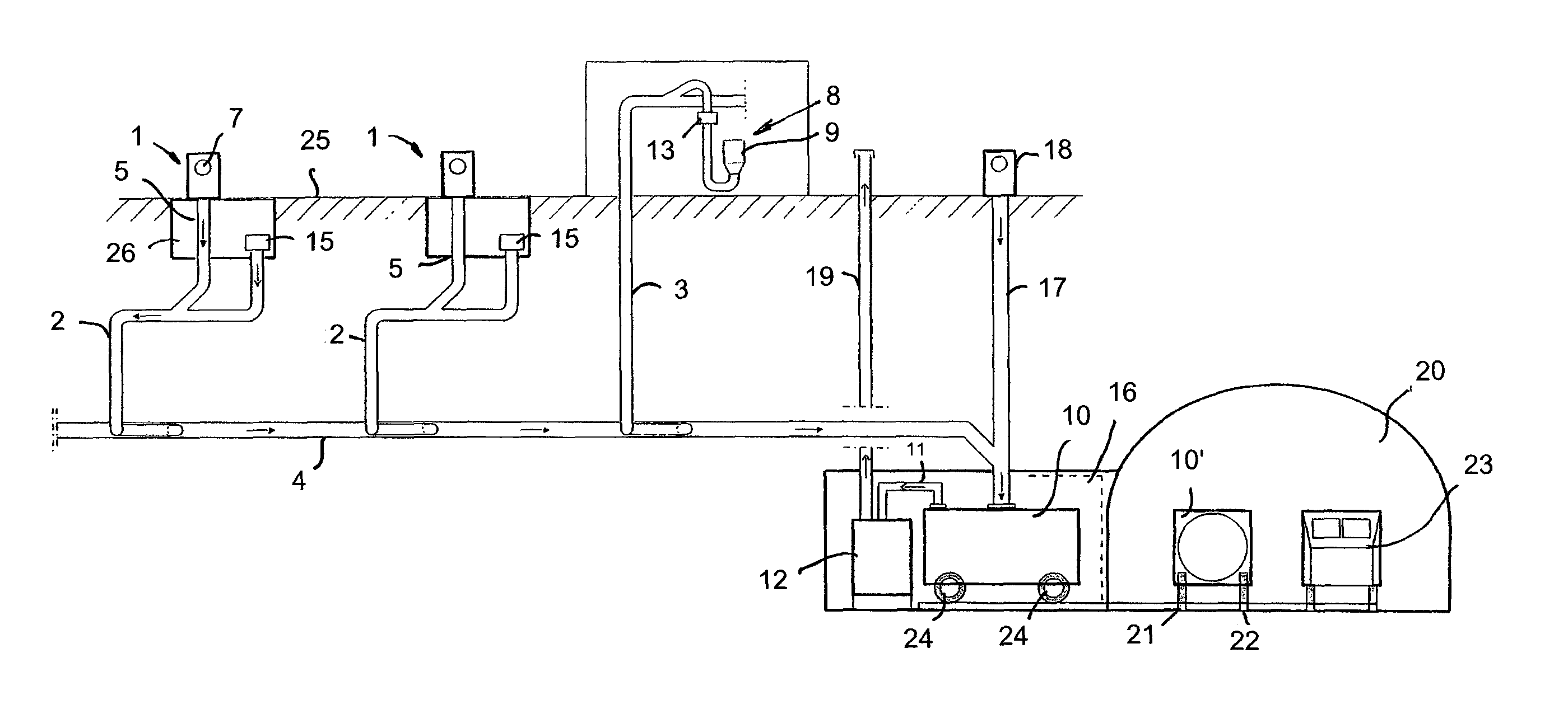
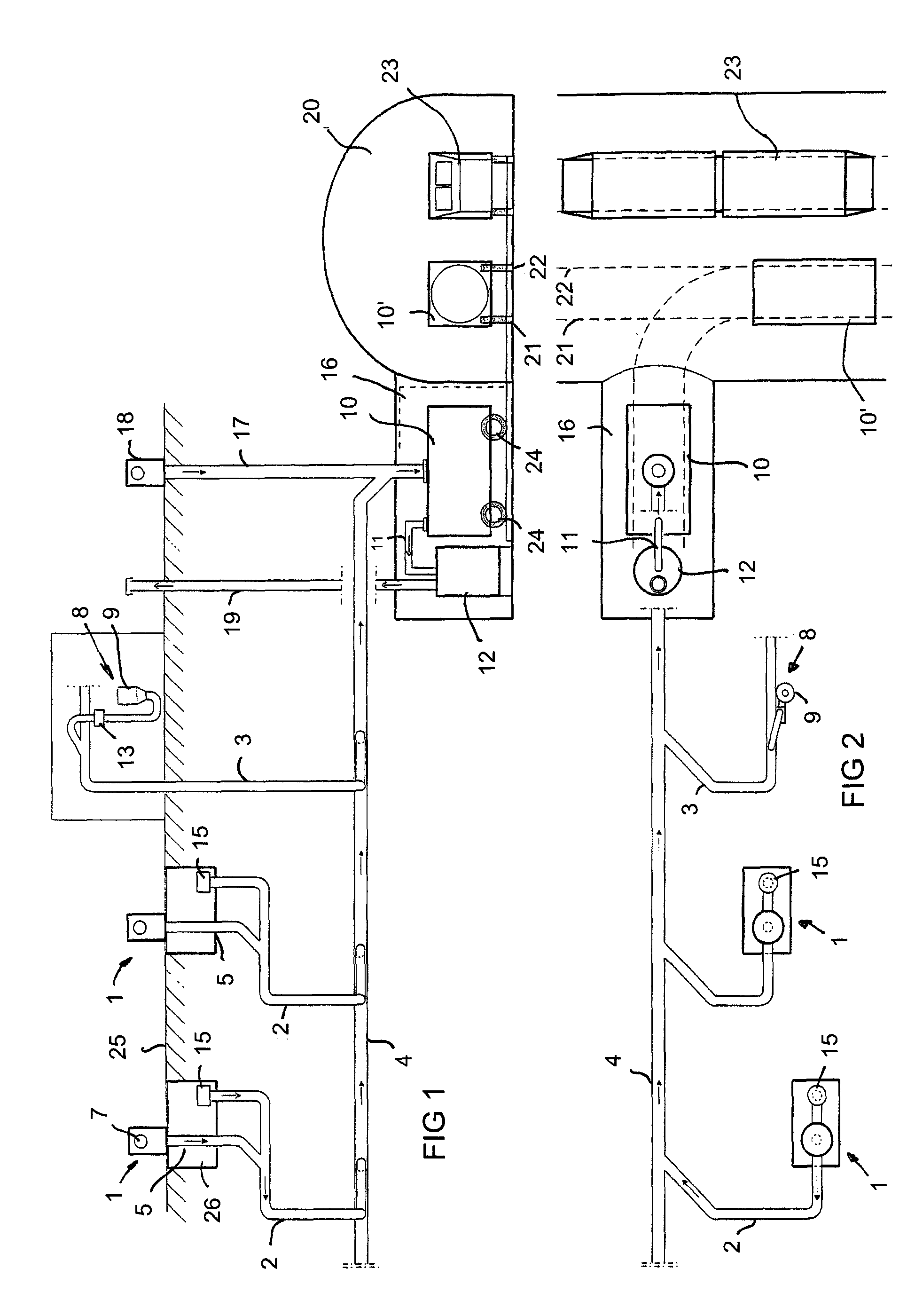
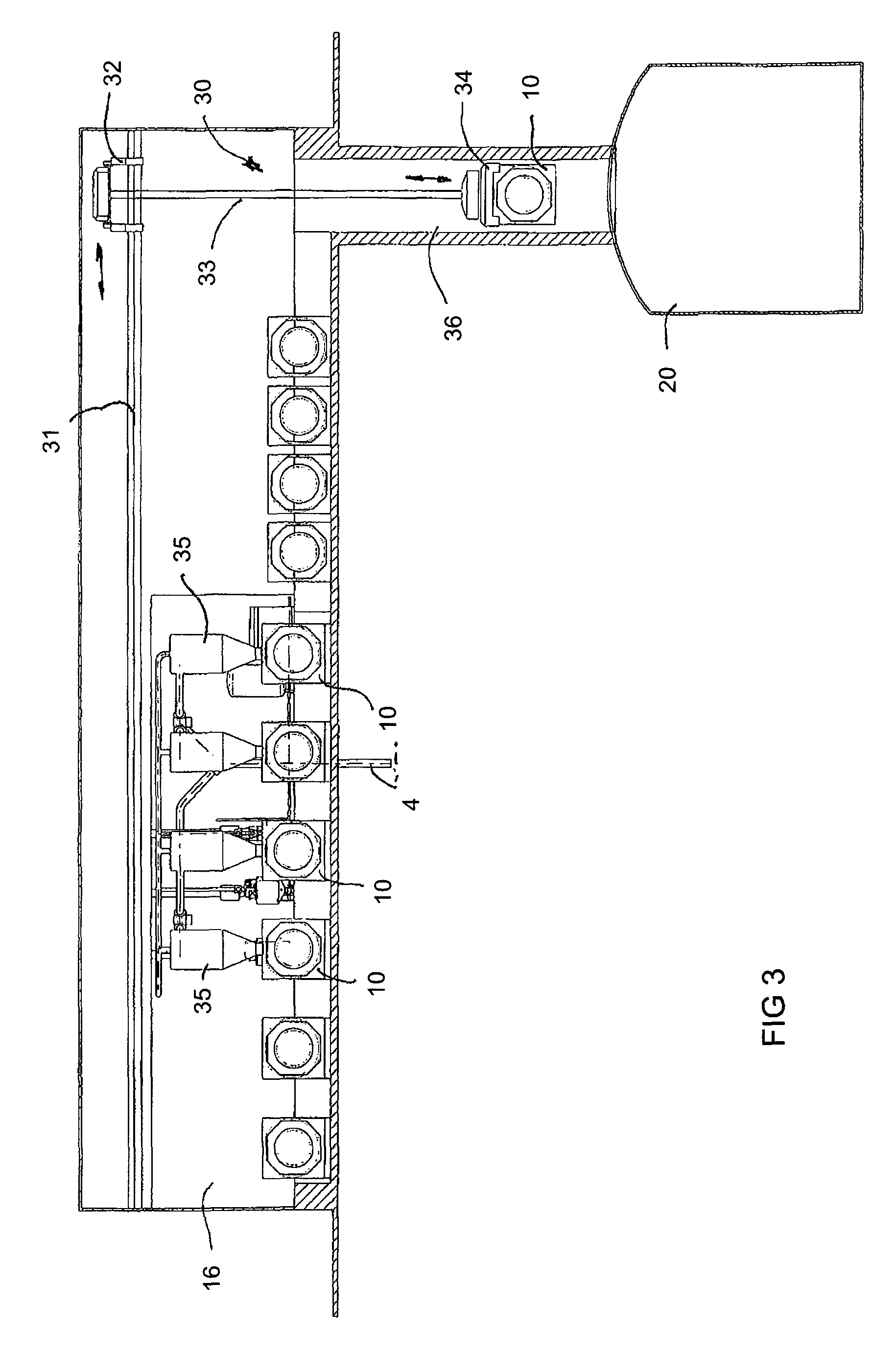
[0015]FIGS. 1 and 2 schematically show a system according to the invention. The figure shows part of a tunnel 20, such as a traffic tunnel, advantageously an underground tunnel, in a recess of which is arranged a waste space 16, particularly a waste room. According to the invention, the tunnel and its vehicle passage is utilised in conveying waste. Along the tunnel network, waste spaces 16 are arranged at suitable points, either in the tunnel space 20 and / or a space connected to it and / or such that there is a conveying connection from the waste spaces 16 for waste or for conveying a waste container in the tunnel space 20. The waste space can thus be a branch of a tunnel which is solely intended for waste conveyance but which is connected to an underground tunnel network. Containers 10 located in the waste spaces 16 are emptied to a waste transport carriage or a waste transport truck which conveys waste along the tunnel network for further processing, such as to a combustion plant, a...


PUM


Abstract

A waste conveying system in which waste is collected / conveyed, e.g. by a suction system, in a waste container (10) of a regional waste space (16) or a transport container in which / from which the waste is then conveyed to further treatment. The waste space (16) and / or the waste container (10) or the transport container is arranged in a tunnel (20), such as a traffic tunnel, advantageously an underground tunnel, or in its vicinity, or there is a conveying connection from them to the tunnel (20) through which the waste is conveyed away.

Description

BACKGROUND OF INVENTION[0001]The invention relates to a waste conveying system.[0002]The invention relates generally to collecting and conveying waste, such as conveying household waste, particularly treating urban waste. Like conventional waste management among dense population, in waste rooms are located waste containers in which household waste is brought, emptied to waste trucks manually and the waste truck takes the waste then to a landfill. However, this causes problems for traffic, the environment and hygiene etc as waste trucks drive around on the roads picking up waste and taking it to the landfill.[0003]Also, systems are known in which waste is conveyed in a piping by means of suction. In these, waste is conveyed for long distances in the piping by suction. This system has, however, proven to use extreme amounts of power and requires a lot of maintenance. Several equivalent arrangements exist. Apparatuses are utilised, inter alia, for conveying waste in different instituti...

Claims


Application Information

Patent Timeline
Patent Type & Authority Patents(United States)
IPC IPC(8): B65G53/10
CPCE04F17/10B65F5/005
Inventor SUNDHOLM, GORAN
Owner MARICAP OY
Why Eureka
Try Eureka