Hybrid electric drive unit, hybrid drive system and control method thereof

a hybrid drive and electric drive technology, applied in the field of hybrid vehicles, can solve the problems of power transmission loss, loss of efficiency of the hybrid mode of the hybrid drive vehicle, and high requirements for material and gear carrier manufacturing, and achieve the effects of simple and effective design, energy saving, and internal connection

Active Publication Date: 2014-05-20
SAIC MOTOR
View PDF13 Cites 18 Cited by
  • Summary
  • Abstract
  • Description
  • Claims
  • Application Information

AI Technical Summary

Benefits of technology

[0013]By means of a simple and effective design, the hybrid drive system provided by the present invention can realize a series / parallel power output of hybrid vehicle by taking advantage of selective power outputs of the engine and two motors properly, and can switch among different operating modes based on different road conditions and battery volumes, so as to achieve energy saving and environment protection for hybrid vehicle and meet demands on system performances as required under different road conditions. At least on the basis of current existing technology, the present invention provides a hybrid drive system which consists of a first shaft, a first clutch, a second clutch, a synchronizer, a first stage decelerating device, a second stage decelerating device, a first gear drive gear, a second gear drive gear, a main traction motor, a integrated starter-generator, an engine and other components, etc., so that a proper connection of individual power sources is realized in the hybrid drive system. Moreover, by means of the arrangement of two clutches, a synchronizer and individual gear shafts, the power source of the main traction motor and transmission components of the hybrid electric drive unit are connected in a proper and compact manner, so as to realize a switch between connection and disconnection of individual hybrid sources and wheel, and operating modes of the hybrid drive system.
[0014]Furthermore, by means of the designs such as the arrangement of the first and second clutches within the space formed by the rotor support of the integrated starter-generator and the first shaft, and the rotor support of the main traction motor and the second shaft, the purpose of saving internal space of the hybrid electric drive unit is realized by the present invention, so that internal structures of the hybrid electric drive unit and drive system can be arranged more compactly and their internal connections can be more efficient and appropriate.

Problems solved by technology

However, this method is complex in power transmission path, and there is a phenomenon that power transmission loss is caused unnecessarily by converting mechanical energy into electric energy and then converting the converted electric energy into mechanical energy to output.
Therefore, if this method is applied for a plug-in hybrid vehicle, it will lead to the loss of efficiency of the hybrid mode of the hybrid drive vehicle.
In addition, since all output power is output by planetary gear carrier of the planetary line, the requirements for the costs on material and the manufacturing of the planet gear carrier are very high.
However, under the condition that a vehicle is in pure electric drive, it is very difficult to meet all design requirements in terms of climbing, acceleration performance and maximum electric travelling speed simultaneously, because the vehicle is driven directly by the main decelerator.
Even so, it is very difficult to ensure the motor could often operate in a higher efficiency region under the urban traveling condition.
In addition, in case when the energy of battery is low, so it is required to change into motor / engine hybrid travelling mode, but due to restrictions on minimum stable rotation speed and torque characteristics of engine, the engine will only be able to operate in a way like that in the above-mentioned series mode in many travelling conditions, such as driving at intermediate or low speed on urban road and ramp road, thus reducing energy utilization efficiency greatly.

Method used


Image

  • Hybrid electric drive unit, hybrid drive system and control method thereof
  • Hybrid electric drive unit, hybrid drive system and control method thereof
  • Hybrid electric drive unit, hybrid drive system and control method thereof

Examples


Embodiment Construction

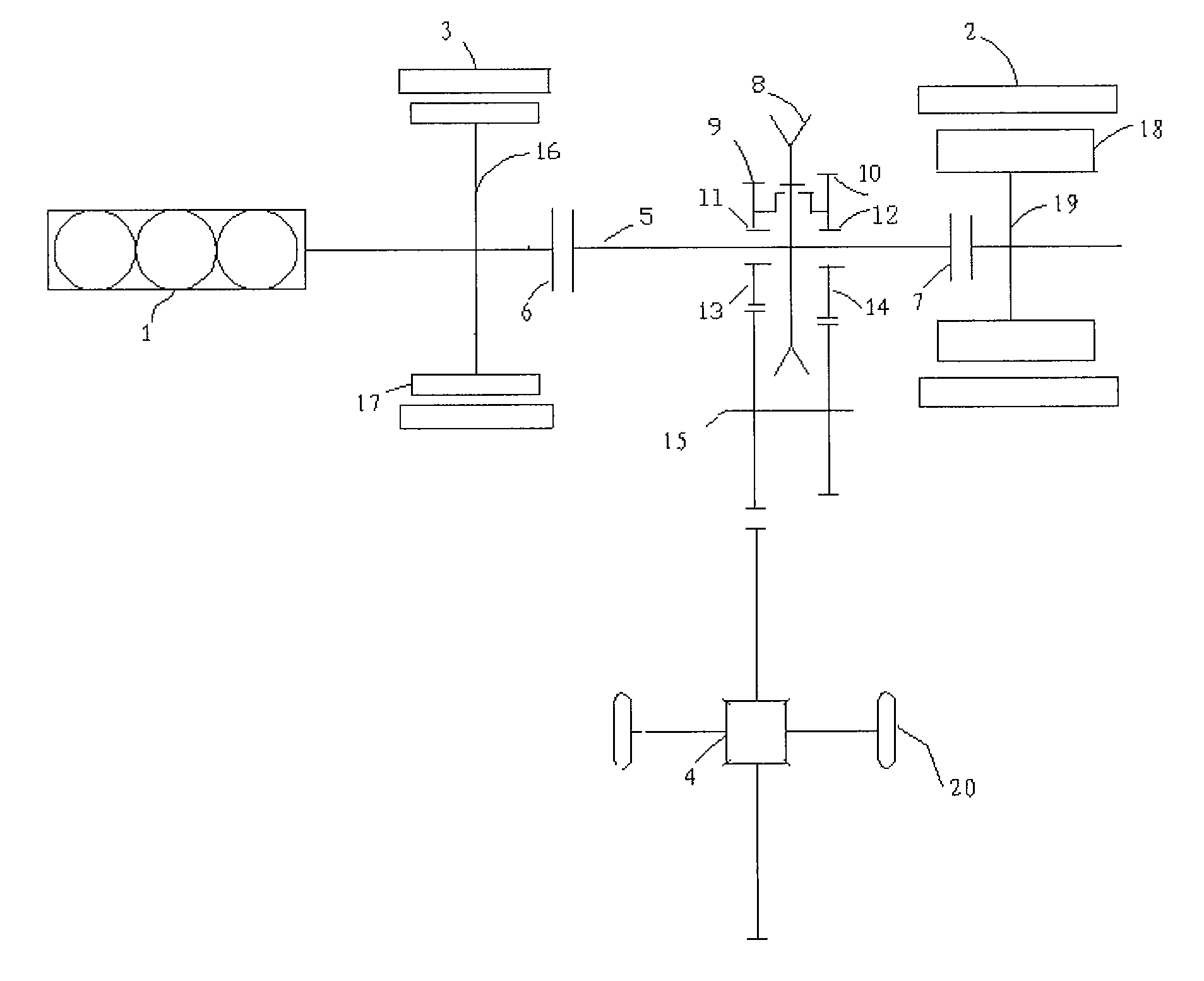
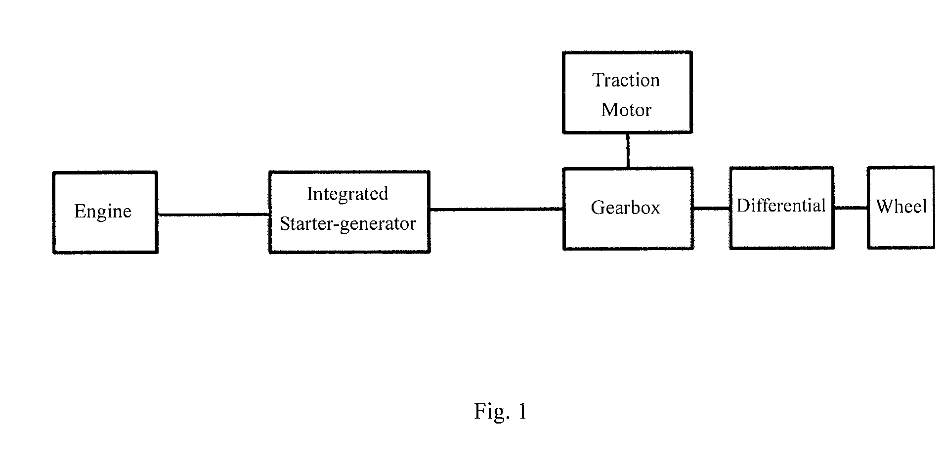
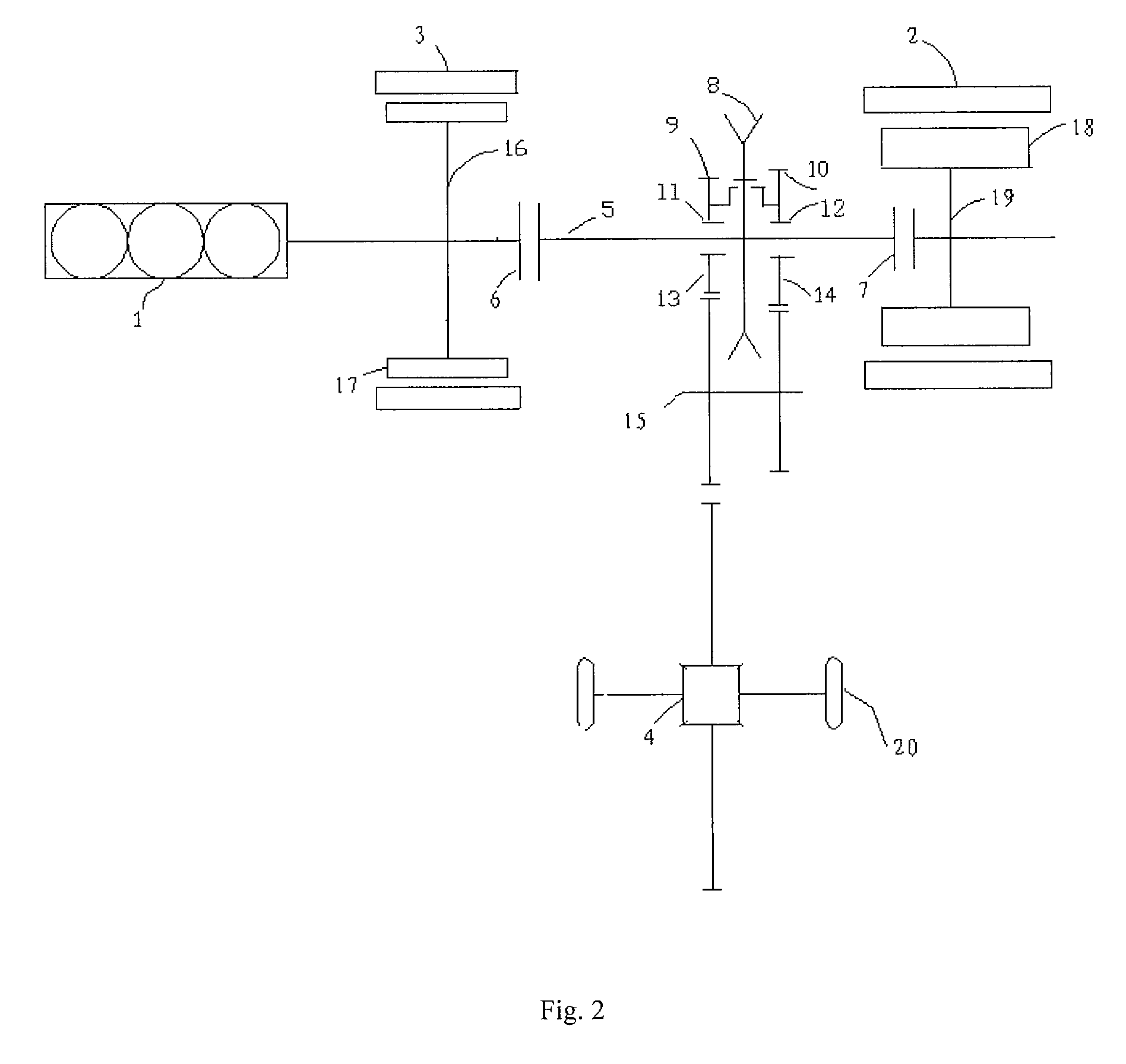
[0019]FIG. 1 illustrates a principle diagram showing connection relationships among components in a drive system of hybrid vehicle according to a specific embodiment of the present invention. It illustrates connection relationships among the engine 1, the wheel 20, the electric drive unit including the first motor 2 and the second motor 3, differential 4 and the other components of a hybrid vehicle applied with the hybrid drive system of the present invention, wherein the engine 1 and the electric drive unit comprise the hybrid drive system of the present invention. Preferably, the first motor 2 is a main traction motor of the hybrid vehicle of the present invention, and the second motor 3 is an integrated starter-generator. Specifically, the engine 1 is connected to the electric drive unit, through which hybrid power is transmitted to the wheel 20 via the differential 4. The specific connection manner and operating modes will be described in detail in the following specific embodim...


PUM


Abstract

A series / parallel hybrid electric drive unit for vehicle comprises an engine (1), a main traction motor (2), an integrated starter-generator (3), a differential (4), a first shaft (main shaft) (5), a first stage decelerating device (9), a second stage decelerating device (10), a first clutch (6), a second clutch (7) and a synchronizer (8). The synchronizer (8) is slidably arranged on the first shaft (5) which is connected to the first stage decelerating device (9) or the second stage decelerating device (10) by the synchronizer (8), respectively. The hybrid electric drive unit of the invention has a compactly-arranged internal structure and an efficient and appropriate internal connection, and a switch between connection and disconnection of respective hybrid power sources and wheels and a shifting among operating modes and gear positions of the hybrid drive system can be realized.

Description

RELATED APPLICATIONS[0001]This application claims the benefit under 35 U.S.C. §371 of International Patent Application No. PCT / CN2010 / 001919, having an international filing date of Nov. 30, 2010, which claims priority to Chinese Patent Application No. 200910199960.4, filed Dec. 4, 2009, the contents of all of which are incorporated herein by reference in their entirety.FIELD OF THE INVENTION[0002]The present invention relates to a hybrid vehicle, in particular a plug-in hybrid vehicle, and more specifically to a hybrid drive unit for vehicle with clutches and a synchronizer coupled in power transmission relationship for shifting, and a corresponding hybrid drive system as well as a driving and shifting method preferably corresponding to the hybrid drive unit and system.BACKGROUND OF THE INVENTION[0003]Since energy saving and environmental protection currently become the main focus in the development of automobile industry, hybrid vehicles have been turned into a main core technology...

Claims


Application Information

Patent Timeline
Patent Type & Authority Patents(United States)
IPC IPC(8): F16H3/091B60W10/11B60W30/19
CPCB60W30/19B60W10/11B60W10/06Y02T10/6269B60K6/448Y02T10/6286B60K6/442B60W10/08Y02T10/6243B60K6/54B60W10/02Y02T10/6234B60K2006/541B60K6/387Y10T74/19223Y10T477/23Y10T477/26Y10T477/24B60K6/547B60L15/2054Y02T10/72B60L50/61B60L50/16Y02T10/62Y02T10/64Y02T10/7072Y02T10/70
Inventor CHEN, HONGCHEN, ZHIXINGAO, WEIMINZHU, JUNLUO, SIDONGGE, HAILONGWANG, JIANCHEN, YANGLONG
Owner SAIC MOTOR
Why Eureka
Try Eureka