Industrial continuous cracking device of plastics

a continuous cracking and plastic technology, applied in the direction of charging devices, mechanical conveying coke ovens, combustible gas coke oven heating, etc., can solve the problems of complex equipment structure, and achieve the effects of low running cost, simple configuration, and small volum

Active Publication Date: 2014-05-20
NIUTECH ENVIRONMENT TECHNOLOGY CORPORATION
View PDF3 Cites 10 Cited by
  • Summary
  • Abstract
  • Description
  • Claims
  • Application Information

AI Technical Summary

Benefits of technology

[0005]The purpose of this invention is: designing a continuous cracking device of plastics, which has a simple configuration, small volume and low running cost.
[0007]In this invention, one of the outer cylinder and the internal cylinder can be designed as the cracking cavity, and the other can be used as the cavity for depositing the returning solid state heat carrier. However, considering the volume of the materials to be transported, the outer cylinder is generally used for cracking, and the internal cylinder is used for the return of the solid state heat carrier. At the same time, because the two cavities are connected, so the solid state heat carrier can be heated when returning, and that can satisfy the temperature demand for the cracking process. In this way, the solid state heat carrier will form a cycle in the cylinder. And that not only simplifies the structure and reduces the space, but also the solid state heat carrier cycling in the cylinder has no heat loss and the operating cost is greatly reduced.
[0010]In order to complement the solid state heat carrier's lost heat in the cracking process and makes it satisfy the request of the again cracking reaction, it can be realized by setting higher temperature in the cylinder. However, for ensuring that the solid state heat carrier can absorb enough heat energy and the heating cost is lower, the heating mechanism should be respectively set in the outer cylinder and the internal cylinder. On the one hand, the internal cylinder's heating mechanism can be set in it's wall, on the other hand, the heating mechanism can also be fixed in the middle of the internal cylinder following its axial direction of. Then, the heating mechanism of the internal cylinder can use the same tube, and it can be as an entity with the internal cylinder. What's more, the two ends of the heating mechanism's prolongations out of the body of the outer cylinder are connected with the drive mechanism.
[0011]After the cracking process, in order to realize the separation of the solid product and the solid state heat carrier, it usually uses the method of setting the screen mesh in the cylinder. When the internal cylinder is used as the passage for transporting the solid state heat carrier, the solid state heat carrier's import mechanism, which is fixed on the import end of the internal cylinder, should be fixed on the top of the screen mesh. Furthermore, in order to conveniently transport the separated solid product, the screen mesh in this invention is designed into tube-shape, and the outside of it has the baffle, which can prevent the solid state heat carrier from flowing to the outside of the screen mesh. There the helical ribbon between the screen mesh's outside wall and the outer cylinder, and the helical ribbon can transport the solid product to the outlet. Furthermore, the inlet side of the internal cylinder should be set in the screen mesh at this time.
[0015]Based on the transmission's need, minor diameter joints can be set between the two ends of the outer cylinder, and the internal cylinder's inner wall, which is corresponding to the joints neighboring with the raw materials' inlet, is fixed with the helical ribbon; the inner wall of the internal cylinder, connecting with the other joint, is set with the helical ribbon, and that can realize the successful transportation of raw materials and the product produced in cracking.

Problems solved by technology

However, in that technology, because the device of the solid state heat carrier's return, the reheating process and the separating mechanism of the cracking solids were set outside of the cracking cavity, which makes the equipment structure more complex.

Method used


Image

  • Industrial continuous cracking device of plastics
  • Industrial continuous cracking device of plastics
  • Industrial continuous cracking device of plastics

Examples


example 1

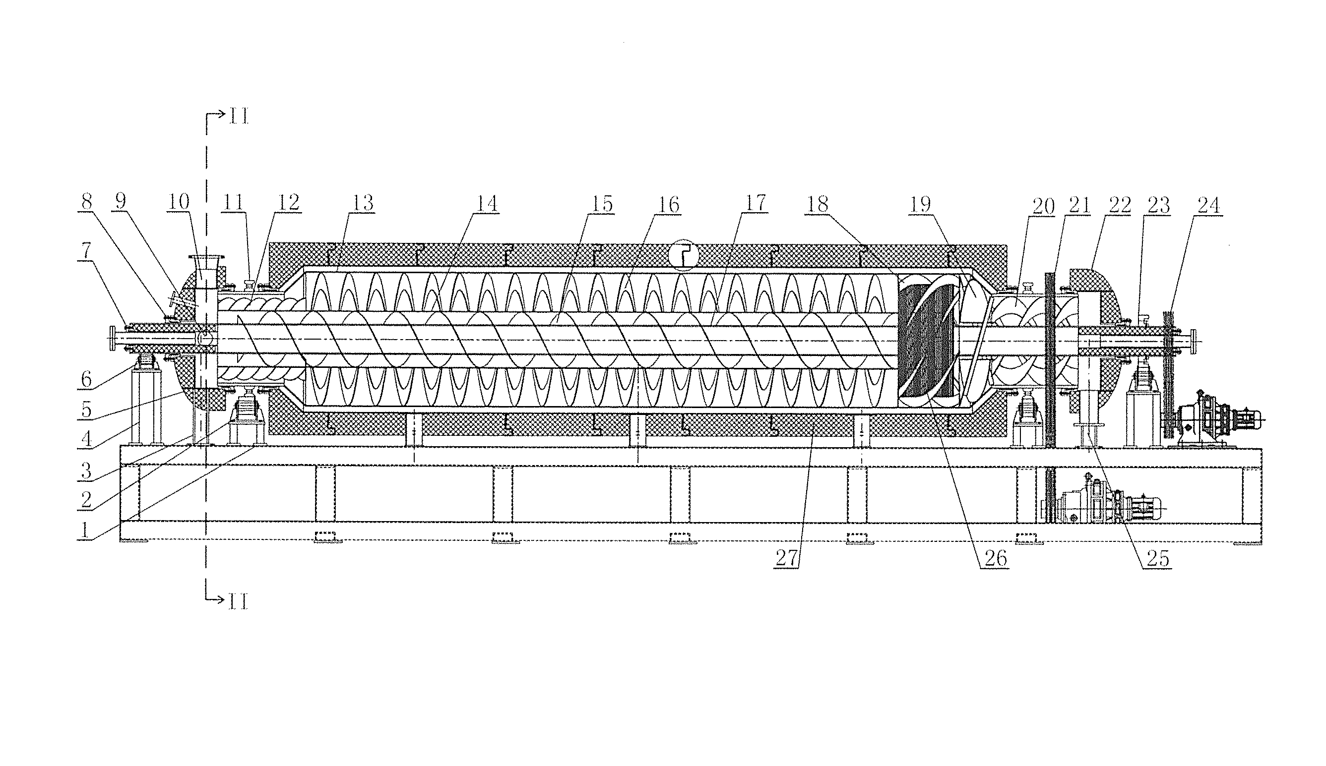
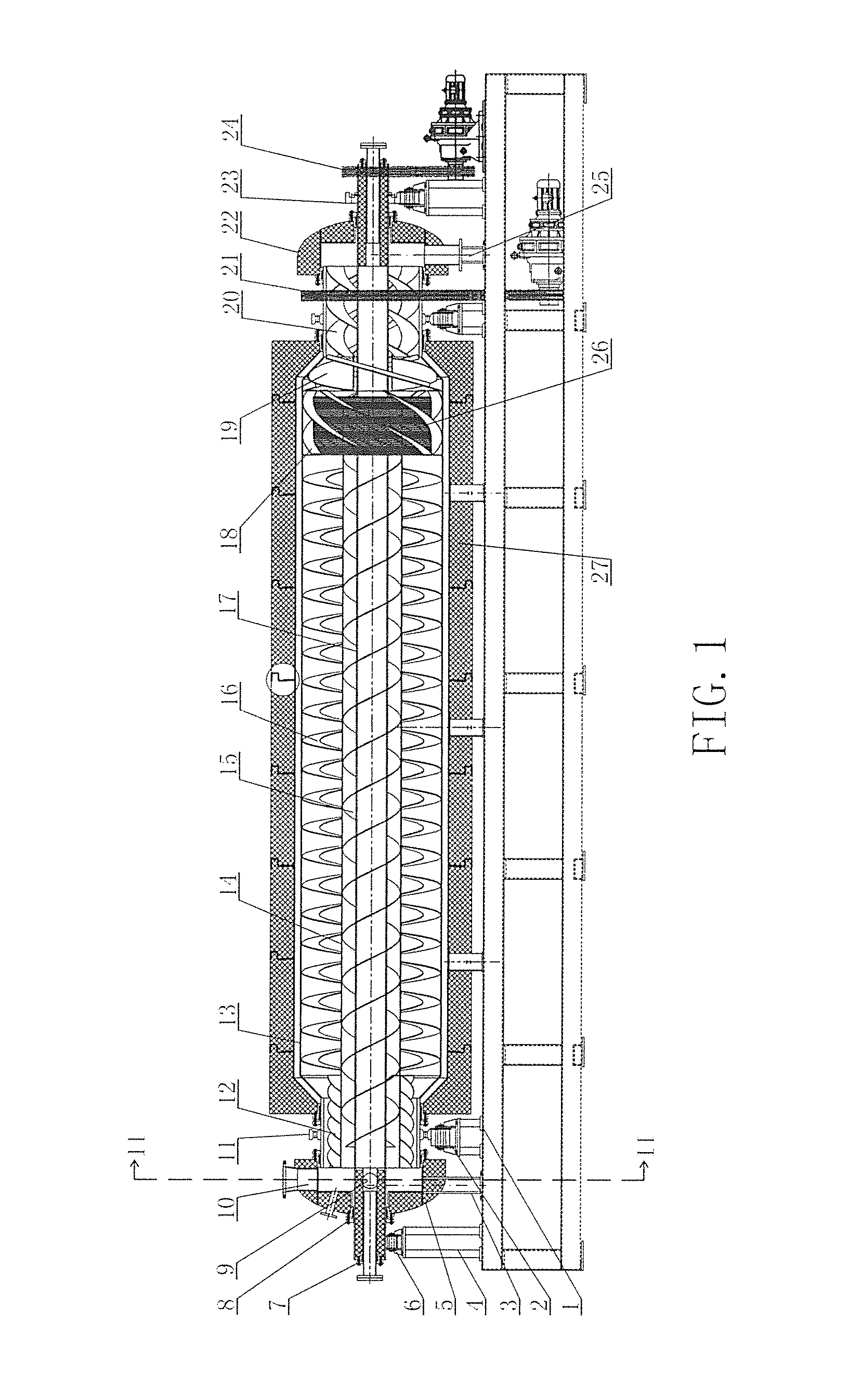
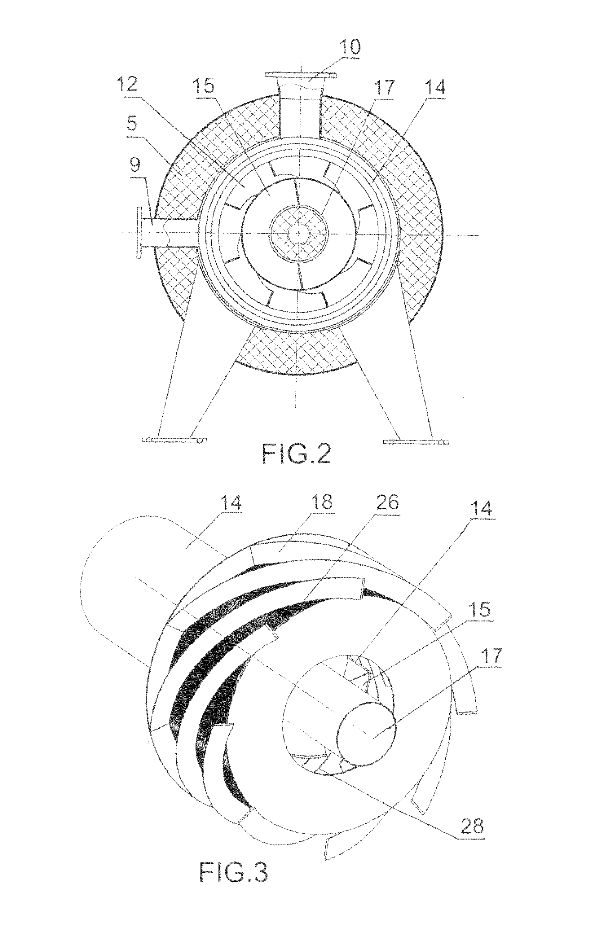
[0023]This example includes the outer cylinder and the internal cylinder, and the two ends of the internal cylinder are communicated with the outer cylinder. The heat mechanism is fixed in the outer cylinder, and the inner wall of the outer cylinder is set with helical ribbon. Inside the internal cylinder is fixed the transportation mechanism whose feeding direction is contrary to that of the outer cylinder. Furthermore, this transportation mechanism adopts the screw form. The liftingsing mechanism is set at the inlet of the internal cylinder, and it can transport the solid state heat carrier from the outer cylinder into the internal cylinder. The screening mechanism used for separating the solid state heat carrier and the solid product produced in cracking, is set in the outer cylinder. What's more, the oil-gas's outlet and the solid product's outlet corresponding with the screening mechanism are set on the outer cylinder.

example 2

[0024]This example includes the outer cylinder and the internal cylinder, and the two ends of the internal cylinder are communicated with the outer cylinder. The heat mechanism is fixed in the outer cylinder, and the inner wall of the outer cylinder is set with helical ribbon. The heat mechanism is fixed on the internal cylinder's outer wall. Inside the internal cylinder is fixed the transportation mechanism whose feeding direction is contrary to that of the outer cylinder. Furthermore, this transportation mechanism adopts the screw form. The lifting mechanism is set at the inlet of the internal cylinder, and it can transport the solid state heat carrier from the outer cylinder into the internal cylinder. The screening mechanism used for separating the solid state heat carrier and the solid product produced in cracking, is set in the outer cylinder. What's more, the oil-gas's outlet and the solid product's outlet corresponding with the screening mechanism are set on the outer cylind...

example 3

[0025]This example includes the outer cylinder and the internal cylinder, and the two ends of the internal cylinder are communicated with the outer cylinder. The heat mechanism is fixed in the outer cylinder, and the inner wall of the outer cylinder is set with helical ribbon. Inside the internal cylinder is fixed the transportation mechanism whose feeding direction is contrary to that of the outer cylinder. Furthermore, this transportation mechanism is the helical ribbon, which is fixed on the internal cylinder inner wall. The lifting mechanism is set at the inlet of the internal cylinder, and it can transport the solid state heat carrier from the outer cylinder into the internal cylinder. The screening mechanism used for separating the solid state heat carrier and the solid product produced in cracking, is set in the outer cylinder. What's more, the oil-gas's outlet and the solid product's outlet corresponding with the screening mechanism are set on the outer cylinder.


PUM

PropertyMeasurementUnit
volumeaaaaaaaaaa
temperatureaaaaaaaaaa
heataaaaaaaaaa

Abstract

This invention is about an industrial continuous cracking device of plastics. The technical program of this invention is as following: it includes the outer cylinder and the internal cylinder, and the two sides of the internal cylinder are connected with the outer cylinder; at least one of the outer cylinder and the internal cylinder is set with heating mechanism, and the helical ribbon is fixed in the inside of the outer cylinder wall; the transport mechanism is fixed in the internal cylinder, with its direction contrary to the outer cylinder's the feeding direction. The structures of this invention are simple, and it can reduce the possessive space. Furthermore, when cycling in the cylinder, the solid heat carrier has no heat energy loss, and that can substantially reduce the operation cost of the equipment.

Description

BACKGROUND OF THE PRESENT INVENTION[0001]1. Field of Invention[0002]This invention is about a continuous cracking device of plastics.[0003]2. Description of Related Arts[0004]Previously, the applicant has developed the continuously cracking technology of plastics and its corresponding equipment, which first adopts the solid state heat carrier to heat the plastics. By using this method, it not only successfully resolves the coking problem in the cracking process, but also realizes the industrial production for the continuous cracking process of plastics. However, in that technology, because the device of the solid state heat carrier's return, the reheating process and the separating mechanism of the cracking solids were set outside of the cracking cavity, which makes the equipment structure more complex.SUMMARY OF THE PRESENT INVENTION[0005]The purpose of this invention is: designing a continuous cracking device of plastics, which has a simple configuration, small volume and low runn...

Claims


Application Information

Patent Timeline
Patent Type & Authority Patents(United States)
IPC IPC(8): C10B49/16C10B53/07C10B1/10
CPCC10G2300/1003C10G1/10C10B53/07C10B49/16Y02P20/143
Inventor NIU, BIN
Owner NIUTECH ENVIRONMENT TECHNOLOGY CORPORATION
Why Eureka
Try Eureka