High density patching system for cable and optical fiber

a patching system and high density technology, applied in the field of communication patching system, can solve problems such as difficult jamming of the jumper, and achieve the effects of improving ergonomics, high density, and high fiber port density

Active Publication Date: 2014-05-20
COMMSCOPE INC
View PDF24 Cites 34 Cited by
  • Summary
  • Abstract
  • Description
  • Claims
  • Application Information

AI Technical Summary

Benefits of technology

[0011]These problems and others are addressed by embodiments of the present invention. One embodiment of the present invention is a high density fiber optic shelf that improves the ergonomic issues by using pivoting adapter panels that allow full utilization of the space located in the rack unit. This provides the potential for higher fiber port density than traditional patch panels.
[0012]One embodiment of the invention employs a standard 1 U type shelf tray with three rows of adapter patch panels that are able to pivot up out of the plane of the rack unit. Other multiple rack unit versions are possible, which could include more than three rows of adapter patch panels. Each patch panel has its own trough for fiber patch cords on the front and a pivot feature inside the shelf to the rear of the “behind the wall” connectors. The pivot feature allows the top and middle position panels to be rotated up, with the top panel rotating more than the middle panel, creating a three tier stagger of the adapter positions. The vertical offset created by the rotated-up tiers gives access for jumper management. When the panels are pivoted down access to the jumpers would be difficult, but clearance is physically available for connector operation. In order to efficiently utilize the panel pivot up feature, the shelf can be a slide out type shelf and be used in the pulled-out position.
[0013]Additional features to make the ultra high density fiber shelf design more usable are pivot angle retention features, which hold the patch panel in the pivoted accessible position until released by the technician, removable patch panels, a modular preterminated patch panel design, and trough cover features for patch cord management.
[0015]One aspect of the invention provides a higher port / adapter density on the patch panels while maintaining easy access to the ports / adapters by technicians and easy labeling and viewing of labeling by technicians.

Problems solved by technology

When the panels are pivoted down access to the jumpers would be difficult, but clearance is physically available for connector operation.

Method used


Image

  • High density patching system for cable and optical fiber
  • High density patching system for cable and optical fiber
  • High density patching system for cable and optical fiber

Examples


Embodiment Construction

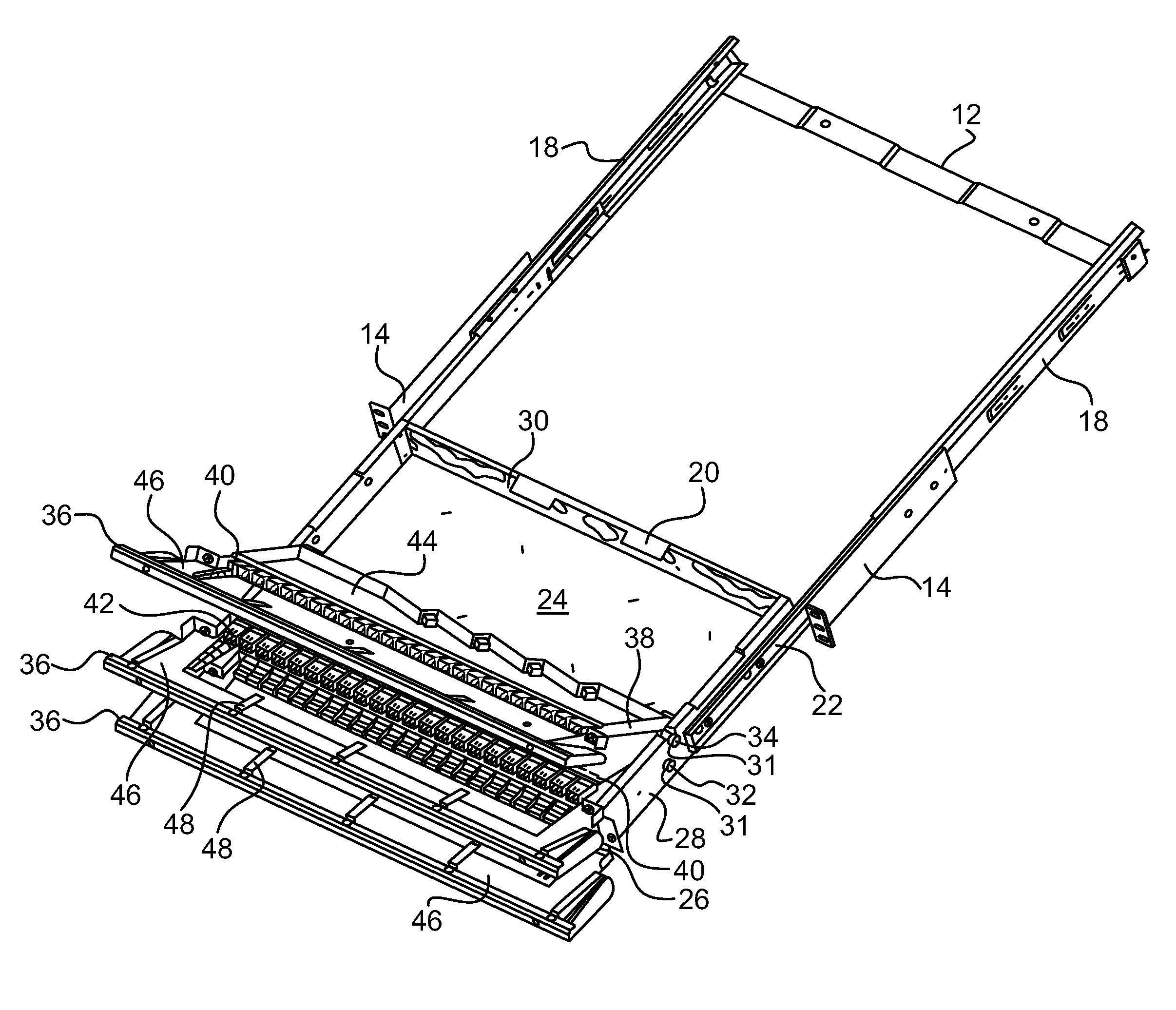
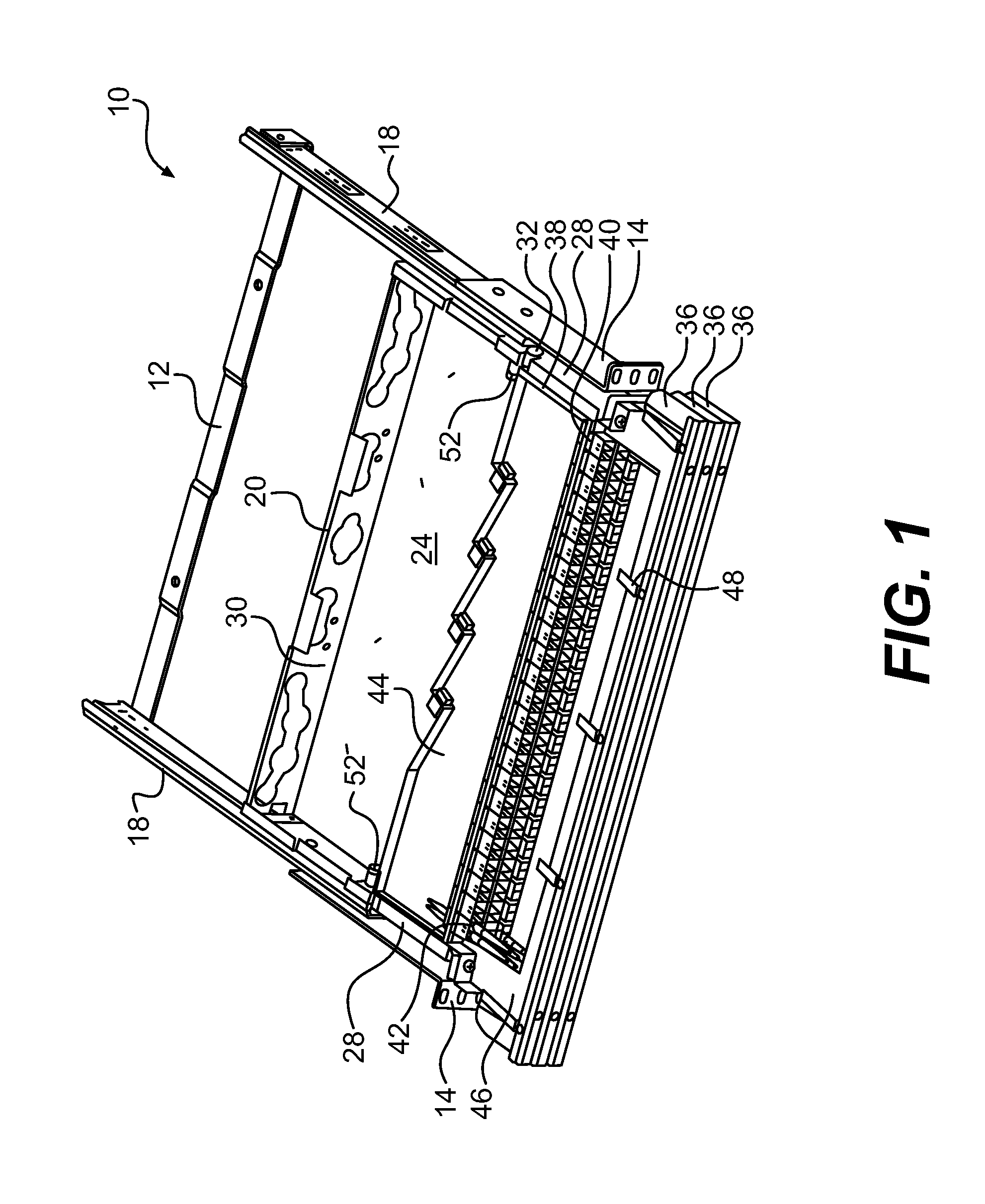
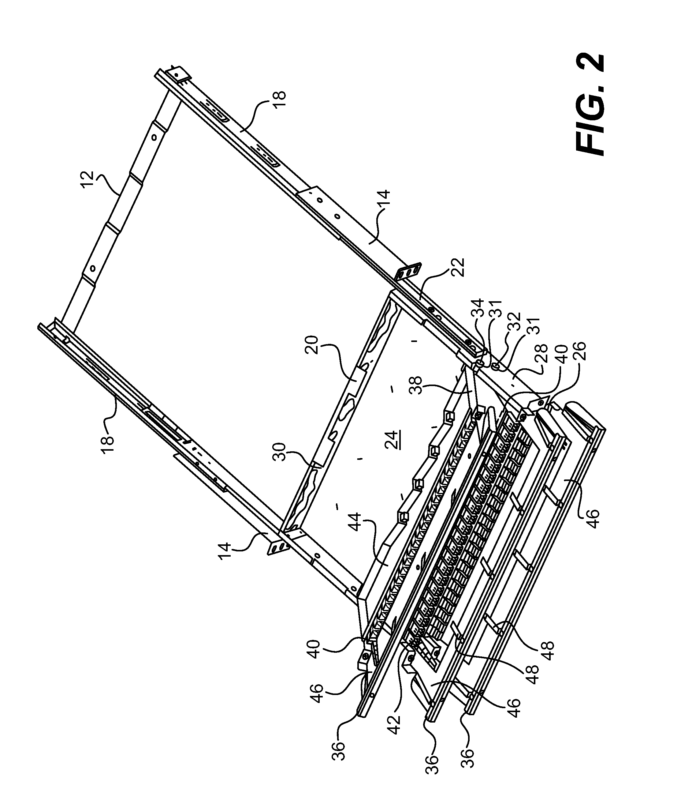
[0030]The present invention now is described more fully hereinafter with reference to the accompanying drawings, in which embodiments of the invention are shown. This invention may, however, be embodied in many different forms and should not be construed as limited to the embodiments set forth herein; rather, these embodiments are provided so that this disclosure will be thorough and complete, and will fully convey the scope of the invention to those skilled in the art.

[0031]Like numbers refer to like elements throughout. In the figures, the thickness of certain lines, layers, components, elements or features may be exaggerated for clarity.

[0032]The terminology used herein is for the purpose of describing particular embodiments only and is not intended to be limiting of the invention. Unless otherwise defined, all terms (including technical and scientific terms) used herein have the same meaning as commonly understood by one of ordinary skill in the art to which this invention belon...


PUM


Abstract

A communication patching system includes a platform configured to support a plurality of cables and a first panel pivotably mounted to the platform, the first panel having at least one holder for securing communications adapters to the first panel. A first set of communications adapters is connected to the platform, and a second set of communications adapters mounted in the at least one holder. The first panel is pivotable between a first position in which the second set of communications adapters is spaced from the first set of communications adapters by a first distance and a second position in which the second set of communications adapters is spaced from the first set of communications adapters by a second distance greater than the first distance.

Description

[0001]The present application claims the benefit of U.S. Provisional Patent Application No. 61 / 185,018, filed Jun. 8, 2009, the entire contents of which is hereby incorporated by reference.BACKGROUND OF THE INVENTION[0002]1. Field of the Invention[0003]The present invention relates to storage / organizing devices used in networking environments. More particularly, the present invention relates to a communications patching system that includes a support for communications lines and one or more panels pivotably mounted to the support, the panels including holders for communications adapters.[0004]2. Description of the Related Art[0005]In communication cabinets and racks, a multitude of cables are interconnected to one another via splices and connectors, such as adapters in the case of fiber optic cables and jacks in the case of copper conductor cables. A cable organization unit having a tray or shelf or similar platform is a convenient way to mount cabling devices, such as splice holder...

Claims


Application Information

Patent Timeline
Patent Type & Authority Patents(United States)
IPC IPC(8): G02B6/00
CPCG02B6/4452H04Q1/133G02B6/4455H04Q1/064H04Q1/131H04Q1/06
Inventor ANDERSON, TIMOTHY W.CASE, RICHARD L.
Owner COMMSCOPE INC
Why Eureka
Try Eureka