
Client apparatus, server apparatus, and program using entity authentication and biometric authentication

a client apparatus and server technology, applied in the field of client apparatus and server apparatus, can solve problems such as unnecessary paths

Active Publication Date: 2014-05-20
TOSHIBA DIGITAL SOLUTIONS CORP +1
View PDF12 Cites 33 Cited by
  • Summary
  • Abstract
  • Description
  • Claims
  • Application Information

AI Technical Summary

Benefits of technology

The present invention provides a way for a client and server to establish a secure session based on entity and biometric authentication without unnecessary handshake paths. The invention also reduces the likelihood of biometric authentication failure and prevents replay attacks by creating an authentication context with a time stamp before the agreement process.

Problems solved by technology

This merely involves performing two handshakes and thus there are unnecessary paths.

Method used


Image

  • Client apparatus, server apparatus, and program using entity authentication and biometric authentication
  • Client apparatus, server apparatus, and program using entity authentication and biometric authentication
  • Client apparatus, server apparatus, and program using entity authentication and biometric authentication

Examples


first embodiment

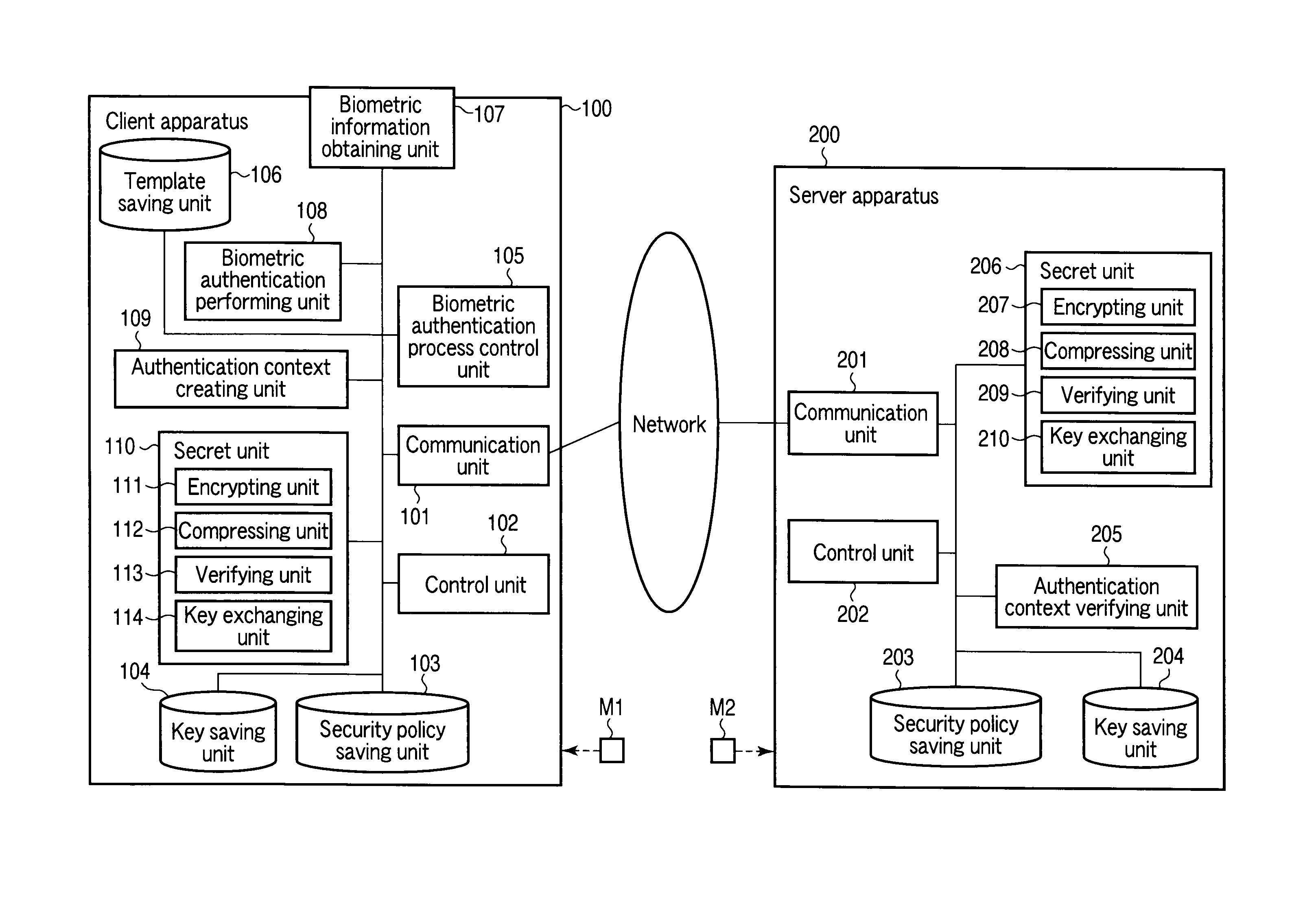
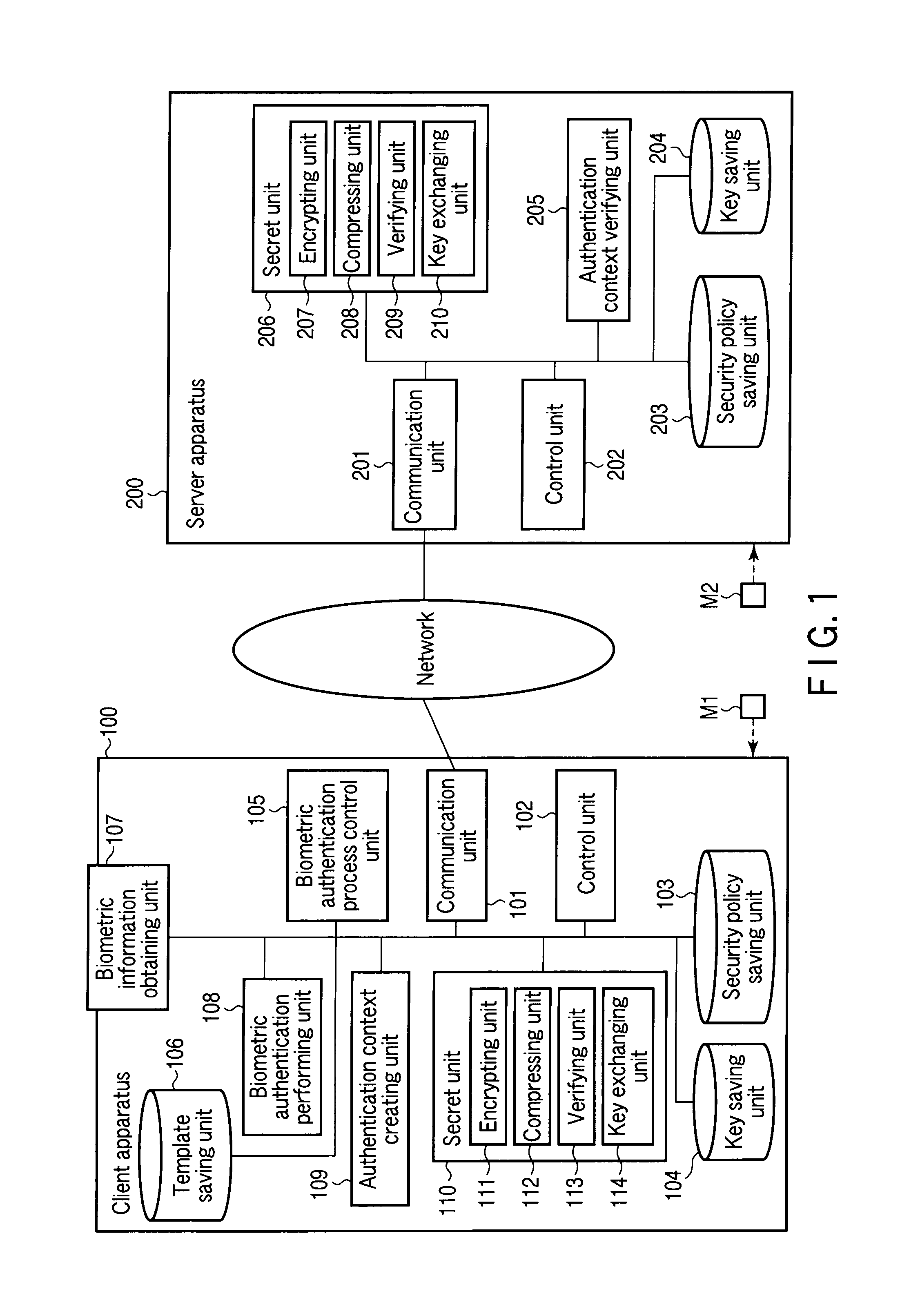
[0062]FIG. 1 is a schematic diagram illustrating a configuration of an authentication system according to a first embodiment of the present invention. The authentication system is configured by a client apparatus 100 and a server apparatus 200 which can communicate with each other over a network such as the Internet.

[0063]The client apparatus 100 includes a communication unit 101, a control unit 102, a security policy saving unit 103, a key saving unit 104, a biometric authentication process control unit 105, a template saving unit 106, a biometric information obtaining unit 107, a biometric authentication performing unit 108, an authentication context creating unit 109, a secret unit 110, an encrypting unit 111, a compressing unit 112, a verifying unit 113, and a key exchanging unit 114.

[0064]The communication unit 101 has the function of performing, by control of the control unit 102, transmission and reception of data with the server apparatus 200 over the Internet.

[0065]The cont...

second embodiment

[0178]FIG. 15 is a schematic diagram illustrating a configuration of an authentication system according to a second embodiment of the present invention, and substantially the same parts as those in FIG. 1 are denoted by the same reference numerals and detailed description thereof is omitted and differing parts are mainly described. In each of the following embodiments, too, likewise overlapping descriptions are omitted.

[0179]The second embodiment is a modification of the first embodiment and is an embodiment of server matching where a result of biometric authentication obtained on the side of a client apparatus 100a is subjected to biometric authentication on the side of a server apparatus 200a.

[0180]Accordingly, compared with the client apparatus 100 illustrated in FIG. 1, the client apparatus 100a is configured such that a template saving unit 106 and a biometric authentication performing unit 108 are eliminated and a control unit 102a and a biometric authentication process contr...

third embodiment

[0232]FIG. 17 is a schematic diagram illustrating a configuration of an authentication system according to a third embodiment of the present invention.

[0233]The third embodiment is a modification of the first embodiment and is an embodiment in which biometric authentication is performed on the side of a client apparatus 100b and a client certificate obtained based on a result of the biometric authentication is sent to a server apparatus 200b to perform client authentication.

[0234]Accordingly, compared with the client apparatus 100 illustrated in FIG. 1, the client apparatus 100b is configured such that a control unit 102b and an authentication context creating unit 109b whose functions are described above are changed are included.

[0235]The control unit 102b has the following functions (f102b-1) to (f102b-7).

[0236](f102b-1) The function of sending, during an agreement process, a Client Hello message (first message) including the fact that a client certificate is to be obtained based ...


PUM


Abstract

A client apparatus receives a message including a random number from a server apparatus during the handshake of agreement process, creates a biometric negotiation message including the biometric authentication method information and sends the biometric negotiation message to the server apparatus. Then, the client apparatus executes a biometric authentication based on biometric authentication method information notified from the server apparatus and encrypts the random number based on the private key. In addition, the client apparatus generates an authenticator from a result of the biometric authentication, the biometric authentication method information, the encrypted random number, and the client certificate, and sends to the server apparatus an authentication context including these. The server apparatus verifies the authentication context and establishes a secure session in one handshake.

Description

CROSS REFERENCE TO RELATED APPLICATIONS[0001]This is a Continuation Application of PCT Application No. PCT / JP2008 / 063911, filed Aug. 1, 2008, which was published under PCT Article 21(2) in Japanese.[0002]This application is based upon and claims the benefit of priority from prior Japanese Patent Application No. 2007-210904, filed Aug. 13, 2007, the entire contents of which are incorporated herein by reference.BACKGROUND OF THE INVENTION[0003]1. Field of the Invention[0004]The present invention relates to a client apparatus, a server apparatus, and a program that establish a secure session. For example, the present invention relates to a client apparatus, a server apparatus, and a program that can establish a secure session based on entity authentication and biometric authentication without generating any unnecessary path associated with two handshakes.[0005]2. Description of the Related Art[0006]One of the protocols for performing cryptographic communication of information on a netw...

Claims


Application Information

Patent Timeline
Patent Type & Authority Patents(United States)
IPC IPC(8): H04L9/32G06F21/00G06F7/04H04L29/06H04L9/00H04L9/08G06F21/32G06F21/33
CPCG06F21/32H04L9/3231H04L9/3263H04L9/3273H04L63/0861H04L63/0823H04L63/166G06F2221/2151H04L9/32
Inventor FUJII, YOSHIHIROIKEDA, TATSUROOKADA, KOJIMORIJIRI, TOMOAKINISHIZAWA, MINORUTAKAMIZAWA, HIDEHISAYAMADA, ASAHIKO
Owner TOSHIBA DIGITAL SOLUTIONS CORP
Learn More