Continuous round baler chambers and conveyor system

a conveyor system and round baler technology, applied in baling, picking devices, agricultural tools and machines, etc., can solve the problems of reducing the overall efficiency of the harvesting system, interrupting continuous harvesting, and affecting so as to improve the efficiency of simultaneous crop harvesting

Active Publication Date: 2014-05-27
CNH IND CANADA
View PDF40 Cites 25 Cited by
  • Summary
  • Abstract
  • Description
  • Claims
  • Application Information

AI Technical Summary

Benefits of technology

[0008]The present invention relates to an agricultural harvester comprising a pickup assembly and two bale chambers operably coupled by a conveyor system. One bale chamber is positioned in the front of the agricultural harvester while the second bale chamber is positioned in the rear of the agricultural harvester. Depending upon the mode of operation, either bale chamber or both bale chambers may be used for bale formation. The design also allows for continuous bale formation to greatly improve the efficiency of simultaneous crop harvesting, bale formation, and bale ejection. While a bale is fully forming in the rear of the baler in a second bale chamber, the first bale chamber can begin partially forming a second bale, this partially formed second bale being sometimes called a core. In some embodiments, a bale carrier is configured around the outlet of the first bale chamber to allow quick ejection of the bale from the first bale chamber and transfer to the second bale chamber. In some embodiments, two bale carriers are configured around the entry point and outlet, respectively, of the second bale chamber to allow clearance of the bale entering and exiting the second bale chamber. In some embodiments, a first bale chamber may be positioned forward of a second bale chamber, wherein the first and second bale chambers are operably coupled by a conveyor system.
[0017]a plurality of baling belt rollers in operable contact with one or more baling belts, the plurality of baling belt rollers comprising two belt rollers movable in the fore and aft directions and independent of movement of any other rollers in the baler; wherein the second and third bale carriers are in operable contact with the one or more baling belts.The downward angle of the conveyor system allows for bale transfer between the first and second bale chambers to be achieved more easily by movement of the conveyor system combined with the downward force of gravity.
[0026]a plurality of baling belt rollers in operable contact with one or more baling belts, the plurality of baling belt rollers comprising two belt rollers movable in the fore and aft directions and independent of movement of any other rollers in the baler; wherein the second and third bale carriers are in operable contact with the one or more baling belts; and wherein each of the first, second, and third bale carriers are movable in the upward and downward directions by a mechanical device operatively coupled to the first pair of arms and / or the second pair of arms of each of the first, second, and third bale carriers; and wherein the second bale carrier forms a front side of a bale in the second bale chamber in its fully closed position, wraps the fully formed bale while in transition to its closed position and receives a partially formed bales from the first bale chamber in an open position; and wherein the third bale forms a rear side of the bale in the second bale chamber in its fully closed position and facilitates evacuation of the bale in an open position.
[0030]In some embodiments, the conveyor system, which facilitates movement of a bale (or bale core) between the first and second bale chambers and is positioned at a downward angle between the first and second bale chambers, comprises at least two rollers and a conveyor belt positioned over the at least two rollers wherein rotation of the at least two rollers causes the conveyor belt to carry harvested crop from the crop harvesting arrangement to the second bale chamber. In some embodiments, the conveyor system comprises at least three, four, or more rollers positioned at a downward angle between the first and second bale chambers. In some embodiments, the conveyor system comprises one or more conveyor belts that carry harvested crop from the crop harvesting arrangement or first bale chamber to the second bale chamber.
[0034]In some embodiments, the baler of the present invention further comprises a motor and at least one of the following: an electronic actuator, a hydraulic cylinder, or a tensioning actuator operatively coupled to the first pair of arms and / or the second pair of arms at least one bale carrier, wherein the at least one electronic actuator, a hydraulic cylinder, or a tensioning actuator facilitate the upward or downward movement of the at least one bale carrier.
[0040]In some embodiments, the crop collection system further comprises a fixed member positioned above the at least one bale carrier for feeding or retracting a flexible material attached along a face of the at least one bale carrier distal to the fixed member. In some embodiments, the fixed member comprises a spring-loaded roller for feeding or retracting the flexible material. In some embodiments the flexible material is used for a safety barrier between the third bale carrier and the area outside the agricultural harvester comprising the bale forming or ejection system or the baler. In some embodiments, the fixed member is operably coupled to at least one motor for facilitating the feeding or retraction of the flexible material. In some embodiments of the invention, the flexible material is a tarp, woven textile, synthetic fiber, or rubber flap which provides a physical barrier between the operating bale chambers and the environment rear to the crop collection system. The physical barrier prevents harvested crop or other materials in the second bale chamber from being ejected out of the crop collection system and prevents individuals or other objects from entering the second bale chamber.

Problems solved by technology

The downtime required to operate the door reduces the overall efficiency of the harvesting system and interrupts continuous harvesting.
Once fully open the weight of the door or panel is typically very heavy, which affects the center of gravity of the equipment, puts additive stress on the tension points, and may cause instability problems if the agricultural harvester is on a hill or slope.
A limitation of this design is the multiple directions toward which the harvested crop must be fed from the harvesting assembly causing a greater likelihood of clogging the entry point of the bale chamber.
The likelihood of clogging the passage with crop also increases with the work of the back-feed mechanism being completed by a single roller.
Another problem is the conventional means to eject the bale from the harvester.
A potential problem with the design is the control of the independent movement of the arms which may increase operator error during operation.
Another limitation of the design is the increased likelihood of silage pile-up and plugging of bale chamber due to a lack of sufficient tension around the bale chamber due to a long belt and long belt pathway.
This problem is likely exacerbated by the movable roller mechanically linked to a spring at the front end of the baler.
Increased silage and harvested crop pile-up toward the front of the baler may contribute to the bale not forming properly while the baler is in operation due to the lack of tension on the bales caused by the movable roller and its related spring-loaded apparatus.

Method used


Image

  • Continuous round baler chambers and conveyor system
  • Continuous round baler chambers and conveyor system
  • Continuous round baler chambers and conveyor system

Examples


Embodiment Construction

[0055]Various terms relating to the methods and other aspects of the present invention are used throughout the specification and claims. Such terms are to be given their ordinary meaning in the art unless otherwise indicated. Other specifically defined terms are to be construed in a manner consistent with the definition provided herein.

[0056]As used in this specification and the appended claims, the singular forms “a,”“an,” and “the” include plural referents unless the content clearly dictates otherwise.

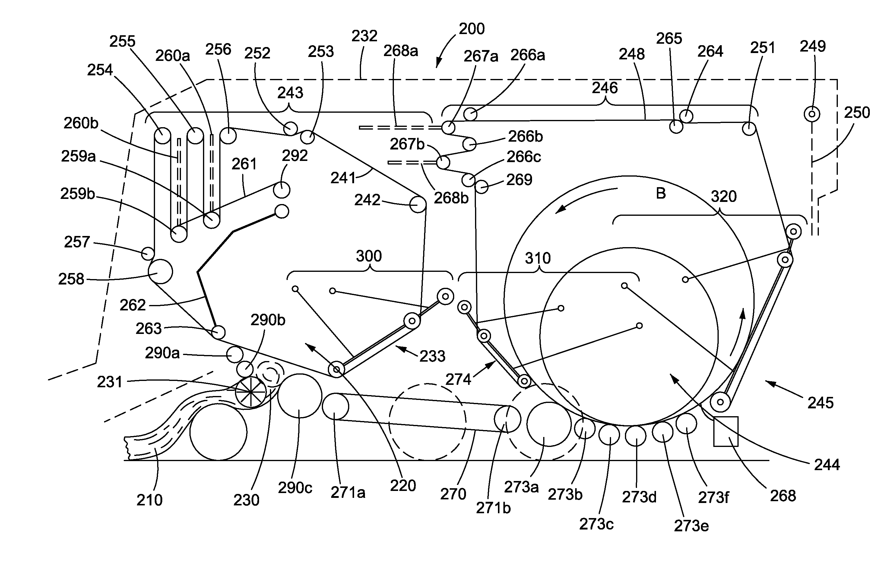
[0057]The term “bale chamber” as used herein is defined as any space within the agricultural harvester that forms a bale of harvested crop. In some embodiments, the sides of the bale chamber are defined by opposite side walls and the bottom of the bale chamber is defined by at least one floor roller that spans transverse to the sidewalls and that partially supports the weight of the bale in the bale chamber. In some embodiments, the bale chamber is also defined in its front region by...


PUM


Abstract

A crop harvesting system for continuous round baling is described that comprises a first and second bale chamber and a conveyor system in operable communication with the first and second bale chambers. The crop harvesting system can comprise at least three bale carriers, at least two serpentine systems to facilitate movement of the bale into and out of the first and second bale chambers. The crop harvesting system can be integrated into an agricultural harvester such as a baler or combine.

Description

TECHNOLOGY FIELD[0001]The present invention relates to an agricultural harvester and a system for the continuous baling of crop. The agricultural harvester and system comprises a crop harvesting assembly, a first and second bale chambers, and a conveyor system that transfers harvested crop from a crop harvesting assembly to one of two bale chambers and that transfers a bale still in formation from a first bale chamber to a second bale chamber. The present invention relates to an agricultural harvester capable of simultaneous harvesting, bale growth, and bale ejection.BACKGROUND OF THE INVENTION[0002]For many years agricultural balers have been used to consolidate and package crop material so as to facilitate the storage and handling of the crop material for later use. A mower-conditioner typically cuts and conditions the crop material for windrow drying in the sun. When the cut crop material is properly dried, an agricultural harvester, such as a round baler, operates over the windr...

Claims


Application Information

Patent Timeline
Patent Type & Authority Patents(United States)
IPC IPC(8): B30B9/00B30B5/06
CPCA01D41/12A01D43/006A01F15/0705A01D46/08A01D39/005A01F15/07A01F15/0883
Inventor ROBERGE, MARTIN, J.
Owner CNH IND CANADA
Why Eureka
Try Eureka