Method for controlling a valve control system with variable valve lift of an internal combustion engine by operating a compensation in response to the deviation of the characteristics of a working fluid with respect to nominal conditions

a technology of internal combustion engine and valve control system, which is applied in the direction of valve operating means/release devices, machines/engines, etc., can solve the problems of varying extent, and bound to decaying the effectiveness of said control strategy, etc., and affecting the efficiency of the engine.

Active Publication Date: 2014-05-27
CENT RICERCHE FIAT SCPA
View PDF14 Cites 1 Cited by
  • Summary
  • Abstract
  • Description
  • Claims
  • Application Information

AI Technical Summary

Problems solved by technology

The effectiveness of said control strategy is, however, bound to decay in time.
This may to a varying extent jeopardize effectiveness of operation of the entire variable valve-control system and of the internal-combustion engine itself, since for example the values of crank angle at which desired events of opening and closing of the valves 2 have been mapped in nominal conditions of the oil (i.e., new oil) and have been chosen so as to guarantee the lowest levels of consumption or else the best performance, as a function of the corresponding operating point of the internal-combustion engine.
All this results generally in intervals of opening of the valves 2 that are markedly different from the ones envisaged during calibration, with consequent repercussions on the efficiency of the engine.
This leads, according to the engine operating point and the drifts in performance in progress, higher consumption levels and / or lower performance, with evident dissatisfaction on the part of the user.

Method used


Image

  • Method for controlling a valve control system with variable valve lift of an internal combustion engine by operating a compensation in response to the deviation of the characteristics of a working fluid with respect to nominal conditions
  • Method for controlling a valve control system with variable valve lift of an internal combustion engine by operating a compensation in response to the deviation of the characteristics of a working fluid with respect to nominal conditions
  • Method for controlling a valve control system with variable valve lift of an internal combustion engine by operating a compensation in response to the deviation of the characteristics of a working fluid with respect to nominal conditions

Examples


Embodiment Construction

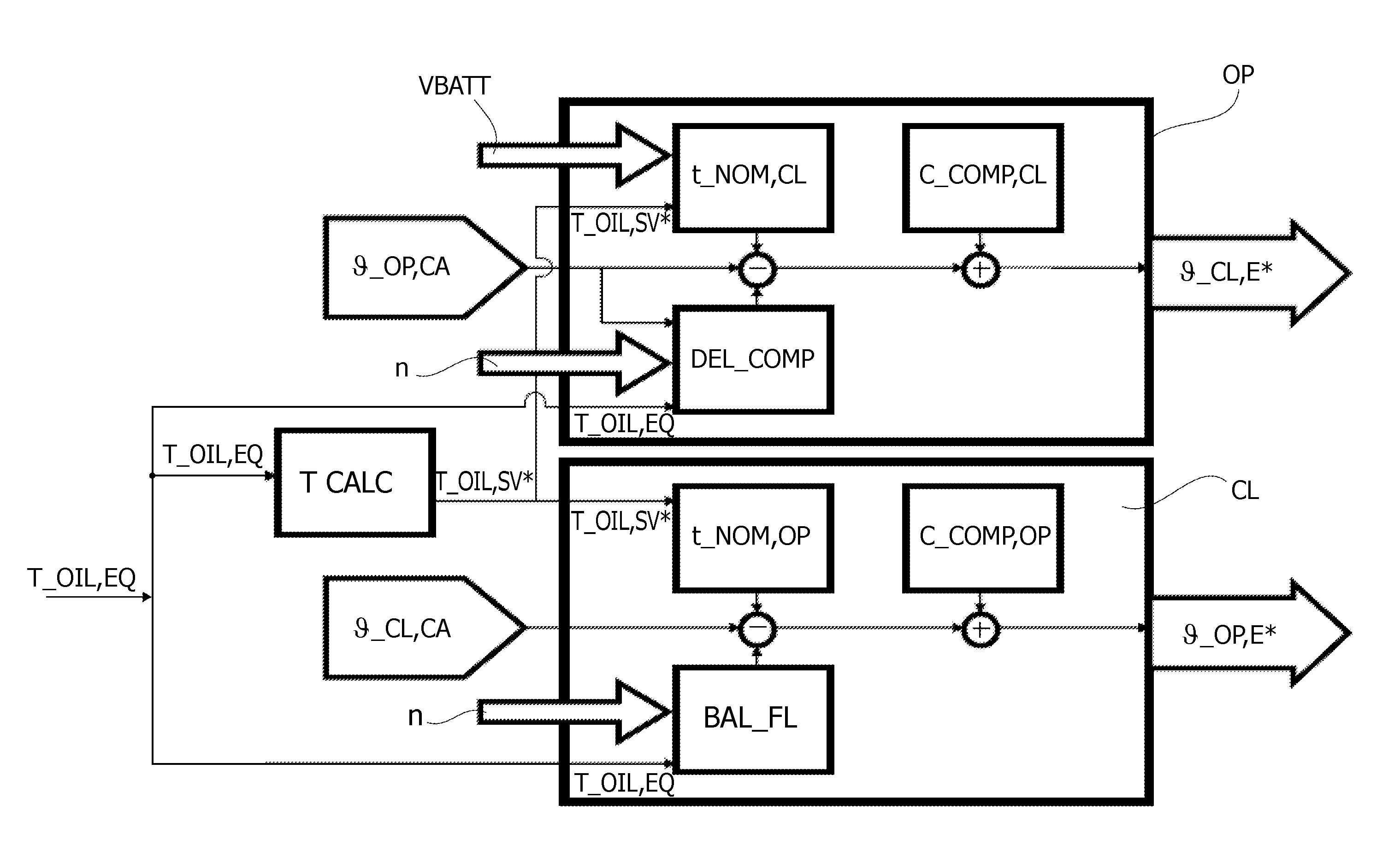
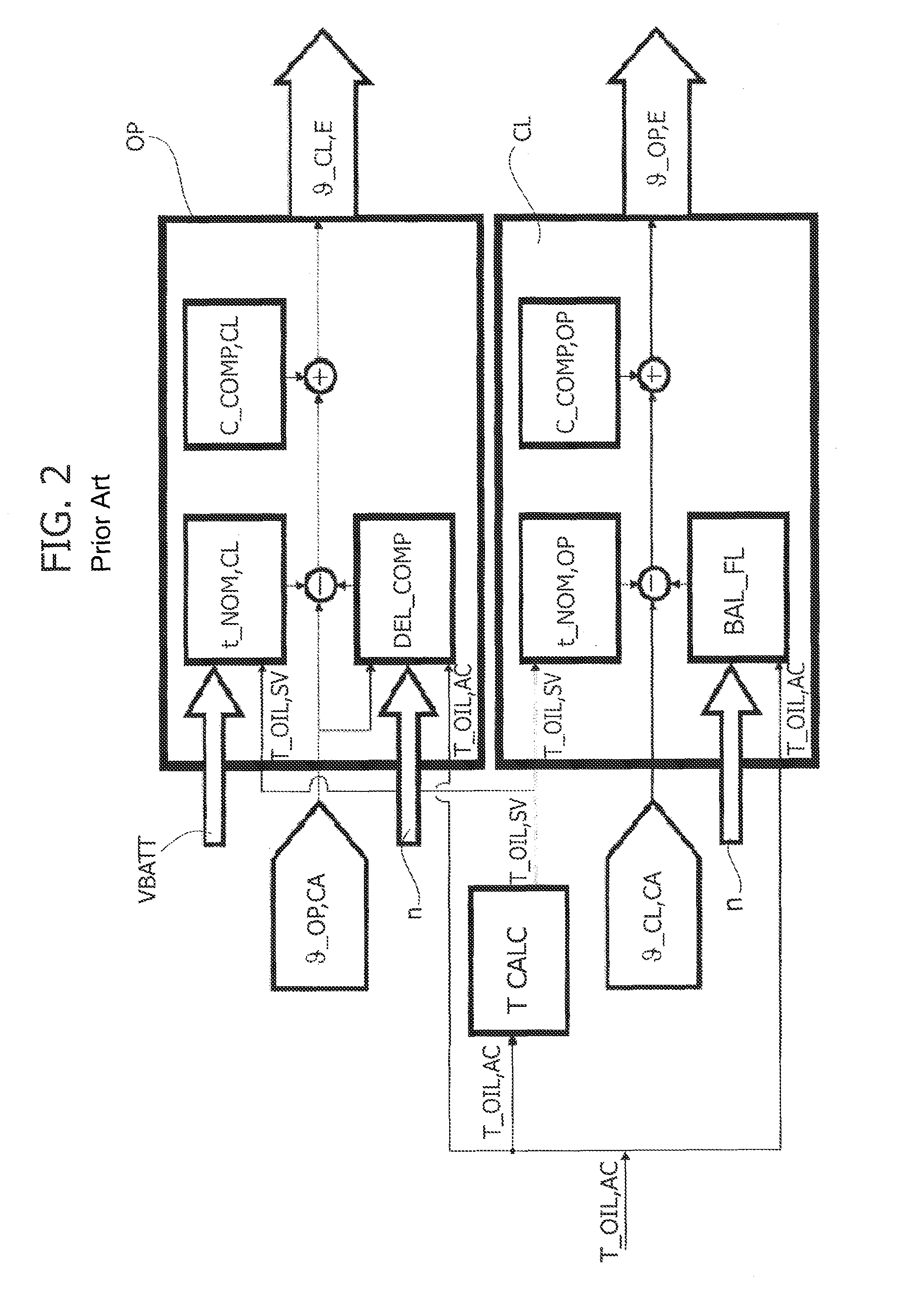
[0084]The calculation method according to the invention is represented schematically in a sequential way in FIGS. 3 and 4. In extreme synthesis, the purpose of the calculation method according to the invention is to modify the input value T_OIL,AC in the block diagram of FIG. 2, substituting it as represented in FIG. 5 with an equivalent value T_OIL,EQ, the calculation and physical meaning of which will shortly be described in detail.

[0085]With reference to FIG. 3, the method according to the invention comprises a first step in which there is brought about a deviation of performance of the solenoid valves 11 due to a degradation of the characteristics of the oil with respect to nominal values thereof.

[0086]The indicator of performance chosen for the calculation is the response time of the solenoid valve 11 of each cylinder of the internal-combustion engine.

[0087]In particular, two characteristic response times are compared, in the case in point:[0088]a measured response time of the ...


PUM


Abstract

A method controls a valve-control system for variable-lift actuation of the valves of an internal-combustion engine, in which the valve-control system includes, for each cylinder of the engine, a solenoid valve for controlling the flow of a hydraulic fluid in the system, and designed manner for determining a real temperature value of the hydraulic fluid. The method includes determining a deviation of performance of the solenoid valves due to a degradation of the characteristics of the hydraulic fluid with respect to nominal values thereof, and substituting for the real temperature value an equivalent temperature value consisting of a temperature value at which the hydraulic fluid having nominal characteristics would produce performance of the solenoid valves corresponding to the performance resulting from the deviation so that each solenoid valve is governed as a function of the equivalent temperature value.

Description

[0001]This application claims priority to EP Patent Application No. 12165785.2 filed 26 Apr. 2012, the entire content of which is hereby incorporated by reference.FIELD OF THE INVENTION[0002]The present invention relates to a method for controlling a valve-control system for variable-lift actuation of the valves of a reciprocating internal-combustion engine, wherein said valve-control system comprises, for each cylinder of said reciprocating engine, a solenoid valve for controlling the flow of a hydraulic fluid in said valve-control system, and further comprises means configured for determining a real temperature value of said hydraulic fluid.PRIOR ART[0003]Systems of the type specified above have been described and illustrated in numerous prior patents filed in the name of the present applicant, such as for example, the European patent No. EP 1555398 B1.[0004]With reference to the annexed FIG. 1, a valve-control system of a hydraulic type for variable-lift actuation of the valves (...

Claims


Application Information

Patent Timeline
Patent Type & Authority Patents(United States)
IPC IPC(8): F01L9/02F01L9/14
CPCF01L2001/34446F01L9/025F01L1/34F01L2001/3443F01L2800/05Y10T137/7758Y10T137/7761F01L9/14
Inventor LANFRANCO, CLAUDIOPUCCIO, MITZI
Owner CENT RICERCHE FIAT SCPA
Why Eureka
Try Eureka