Eureka AIR delivers breakthrough ideas for toughest innovation challenges, trusted by R&D personnel around the world.

Structural nacelle

a technology of nacelles and turbofans, which is applied in the direction of mechanical equipment, machines/engines, transportation and packaging, etc., can solve the problems of affecting the performance of the various stages of the turbojet, affecting the performance of the downstream portion, and causing a lot of curvature, so as to facilitate the transmission of longitudinal forces

Inactive Publication Date: 2014-06-03
AIRCELLE
View PDF10 Cites 6 Cited by
  • Summary
  • Abstract
  • Description
  • Claims
  • Application Information

AI Technical Summary

Benefits of technology

[0012]Therefore, by allowing the pylon to be directly attached to a structure of the nacelle instead of attaching it directly to the turbojet, it is the nacelle which supports the turbojet. In this manner, the turbojet does not have to sustain and transmit the deformations of the nacelle and vice versa. As explained above, it is then possible to optimize the clearance existing between the fan blades and the blades inside the turbojet and their respective casings in order to improve the performance of the propulsion system.
[0036]The presence of such thrust-absorbing link rods mounted obliquely makes it easier to transmit longitudinal forces to the pylon.

Problems solved by technology

These stresses applied to the propulsion system are transmitted to the turbojet and cause deformations of casings which directly impact the performance of the various stages of the turbojet.
More particularly, in the case of a propulsion system called a wasp-waisted propulsion system, that is to say having a long downstream portion that is relatively thin relative to the intermediate and air intake structures, these stresses result in a particularly harmful deformation called a “banana-shaping” deformation, the downstream portion curving considerably.
This results in a portion of the supply air that is not compressed by the blades because it escapes through this considerable clearance.

Method used


Image

  • Structural nacelle
  • Structural nacelle
  • Structural nacelle

Examples


Embodiment Construction

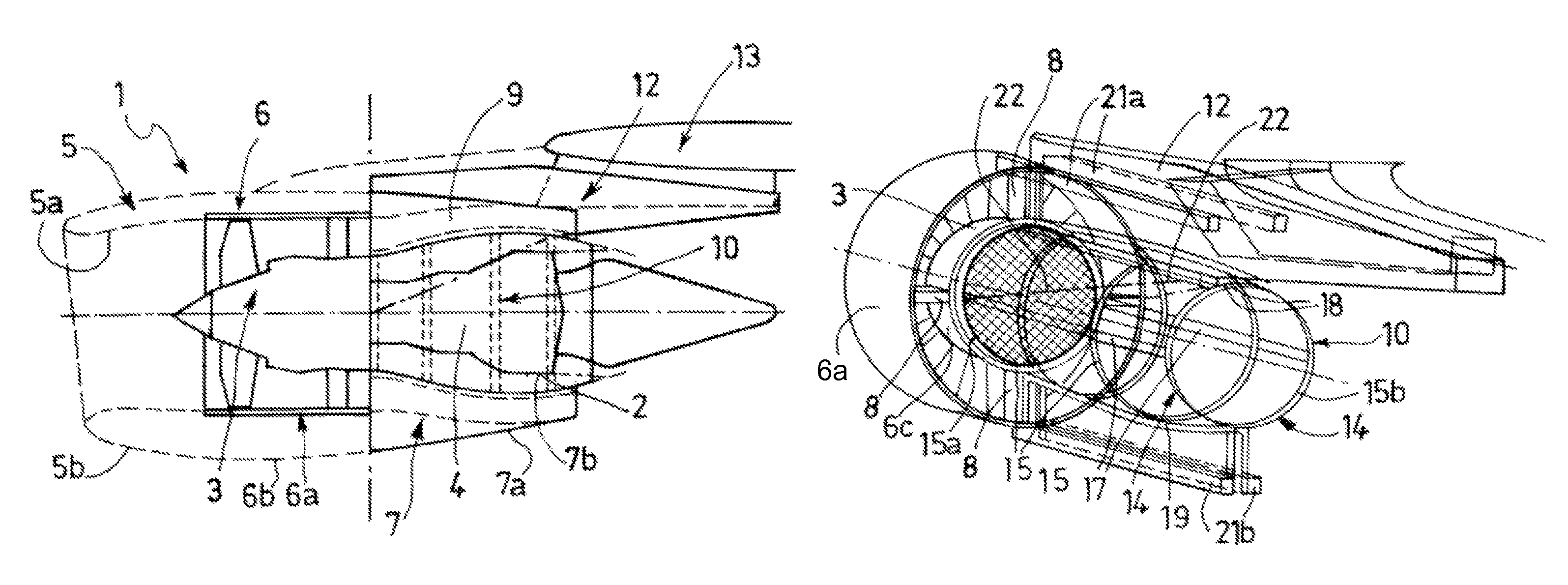
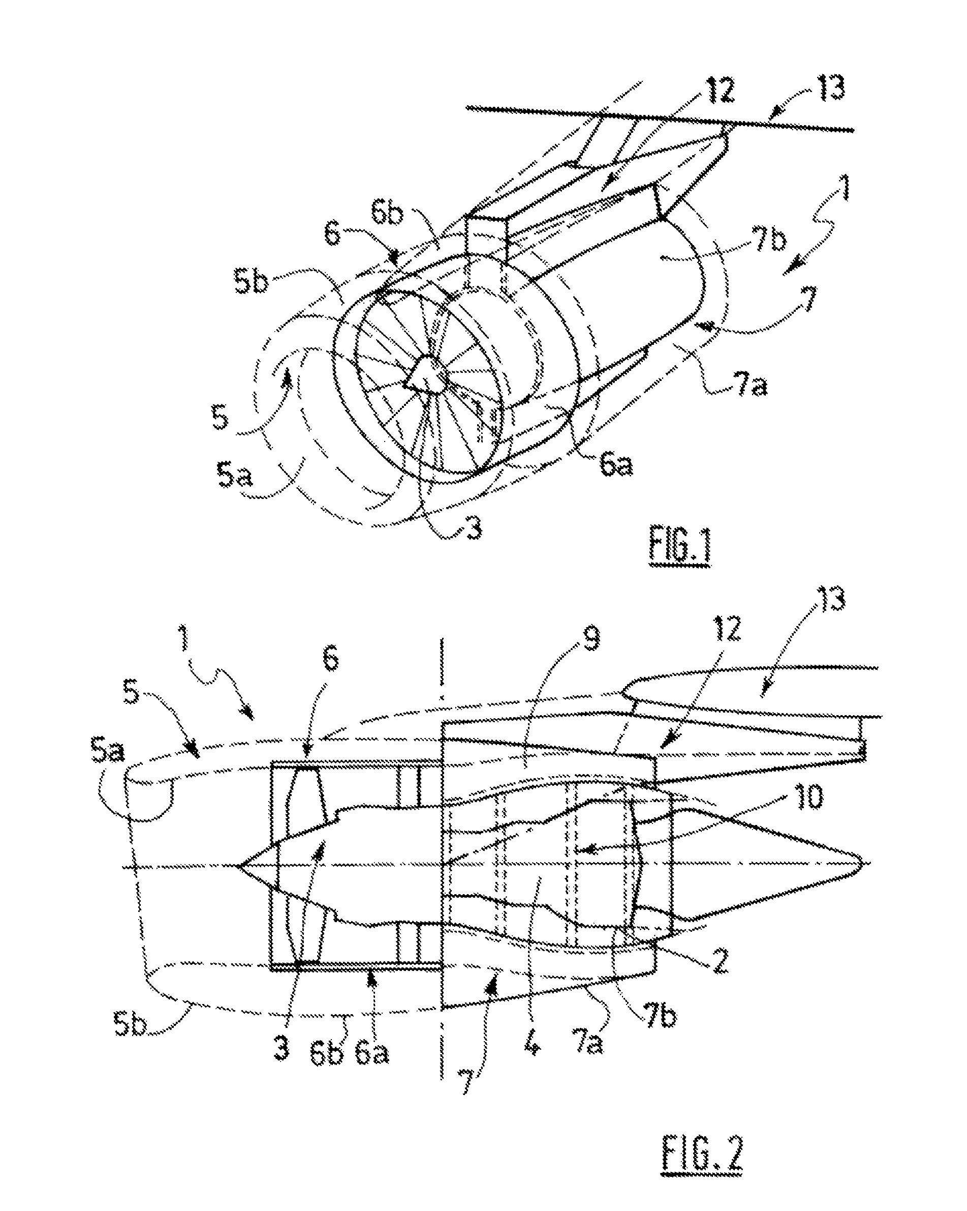
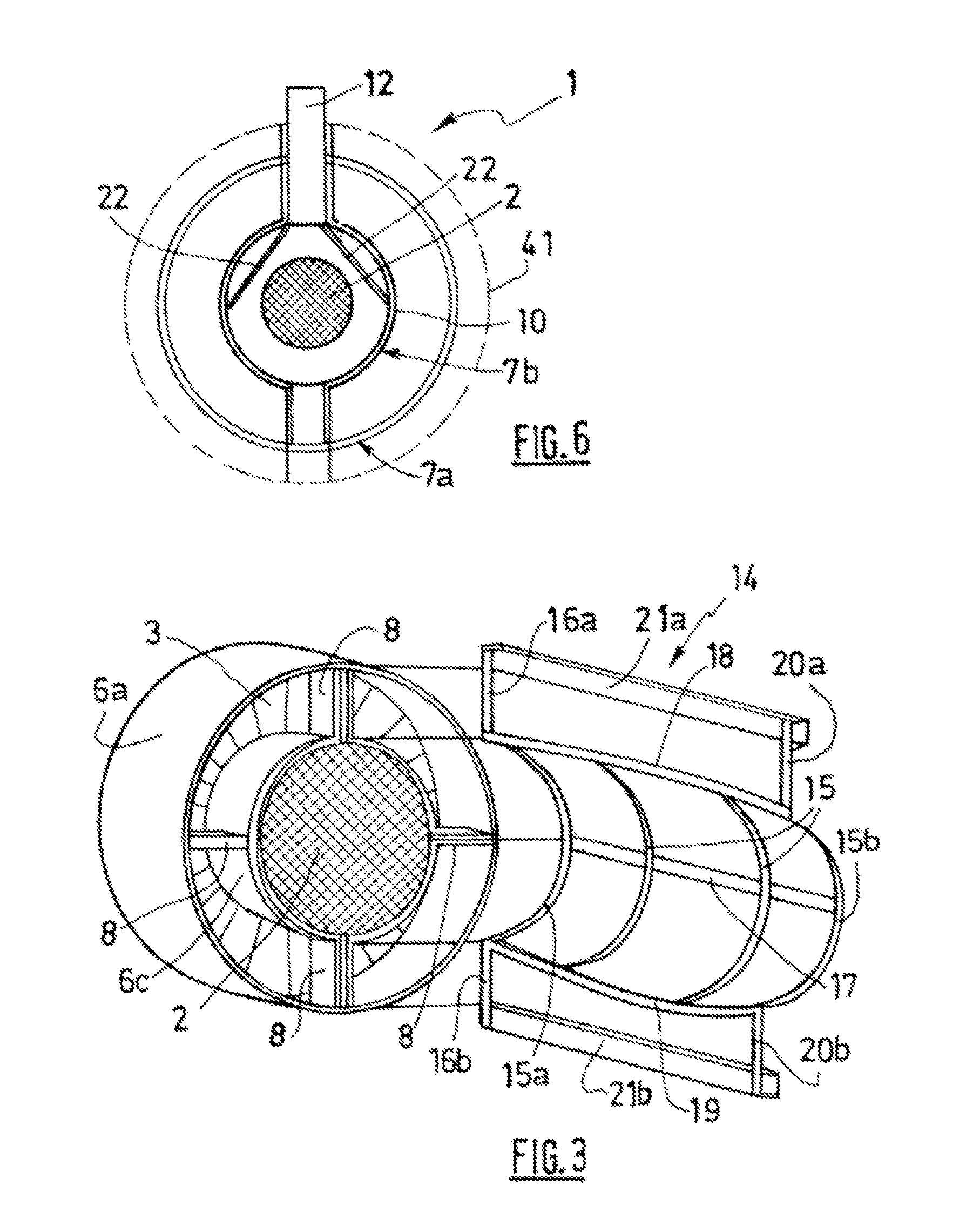
[0056]FIGS. 1 and 2 represent a nacelle 1 for a turbofan 2.

[0057]The nacelle 1 forms a tubular housing for a turbofan 2 and is used to channel the air flows that it generates by means of the air foils of a fan 3, namely a hot air flow passing through a combustion chamber 4 of the turbojet 2 and a cold air flow traveling outside the turbojet 2.

[0058]The nacelle 1 has a structure comprising a front section forming an air intake 5, a mid-section 6 surrounding the fan 3 of the turbojet 2, and a rear section 7 surrounding the turbojet 2 and comprising a thrust reverser system.

[0059]The air intake 5 has an internal surface 5a designed to channel the intake air and a fairing external surface 5b.

[0060]The mid-section 6 comprises, on the one hand, an internal casing 6a surrounding the fan 3 of the turbojet 2, and, on the other hand, a fairing external structure 6b of the casing extending the external surface 5b of the air intake section 5. The casing 6a is attached to the air intake section...


PUM


Abstract

The present invention relates, on the one hand, to a nacelle (1) for a double flow turboreactor (2) comprising a front air intake section (5), a median section (6) intended for surrounding a fan (3) of the turboreactor and a rear section (7), said rear section having an internal structure (7b) intended for serving as a housing to a rear portion of the turboreactor, characterized in that the internal structure possesses attachment means suitable for enabling the nacelle to be fastened to a pylon (12) intended to be connected to a fixed structure (13) of an aeroplane on at least one portion of said internal structure, and on the other hand, to a propellant assembly and to an aircraft provided with such a nacelle.

Description

TECHNICAL FIELD OF THE INVENTION[0001]The present invention relates to a nacelle for a turbofan.BRIEF DISCUSSION OF RELATED ART[0002]An aircraft is propelled by several turbojets each housed in a nacelle also accommodating an assembly of associated actuation devices linked to its operation, such as a thrust reverser device, and performing various functions when the turbojet is in operation or stopped.[0003]A nacelle usually has a tubular structure comprising an air intake upstream of the turbojet, a mid-section designed to surround a fan of the turbojet, a downstream section accommodating thrust reverser means and designed to surround the combustion chamber of the turbojet, and is usually terminated by an exhaust nozzle whose outlet is situated downstream of the turbojet.[0004]Modern nacelles are designed to accommodate a turbofan capable of generating, by means of the air foils of the fan in rotation, a flow of hot air (also called the main flow) originating from the combustion cha...

Claims


Application Information

Patent Timeline
Patent Type & Authority Patents(United States)
IPC IPC(8): B64D27/00F01D25/30
CPCB64D27/18B64D29/00
Inventor VAUCHEL, GUY BERNARDGIBOUIN, ANNE-LAUREFASSIER, REGISJORET, JEAN-PHILIPPECOLLIER, JEROMELEFORT, GUILLAUMECHOUARD, PIERRE-ALAIN
Owner AIRCELLE
Why Eureka
Eureka Blog
Learn More