Optical connector and connector connection system

a technology of optical connectors and connection systems, applied in the direction of optical elements, coupling device connections, instruments, etc., can solve the problems of difficult to narrow the spacing between circuit boards, and achieve the effect of reducing the thickness dimension

Inactive Publication Date: 2014-06-03
THE FUJIKURA CABLE WORKS LTD
View PDF27 Cites 11 Cited by
  • Summary
  • Abstract
  • Description
  • Claims
  • Application Information

AI Technical Summary

Benefits of technology

[0014]Additionally, it is also possible to adopt a configuration in which the housing and the engaging member are provided with latch structures which engage with each other by engaging protrusions and engaging recesses, and the engaging protrusions abut edges of the engaging recesses, thereby regulating forward or rearward movement of the housing with respect to the engaging member.
[0020]According to the present invention, the optical connector can be fastened to the receiving-side optical connector without using an adapter. Moreover, the optical connector can easily realize reduction (slimming) of the thickness dimension compared to the MPO-type optical connector.

Problems solved by technology

Additionally, since the thickness of a connector (plug) itself is large, in a case where a plurality of circuit boards is arranged in parallel, it is difficult to narrow the spacing between the circuit boards.

Method used


Image

  • Optical connector and connector connection system
  • Optical connector and connector connection system
  • Optical connector and connector connection system

Examples


Embodiment Construction

[0057]An optical connector and a connector connection system of one embodiment of the present invention will now be described below with reference to the drawings.

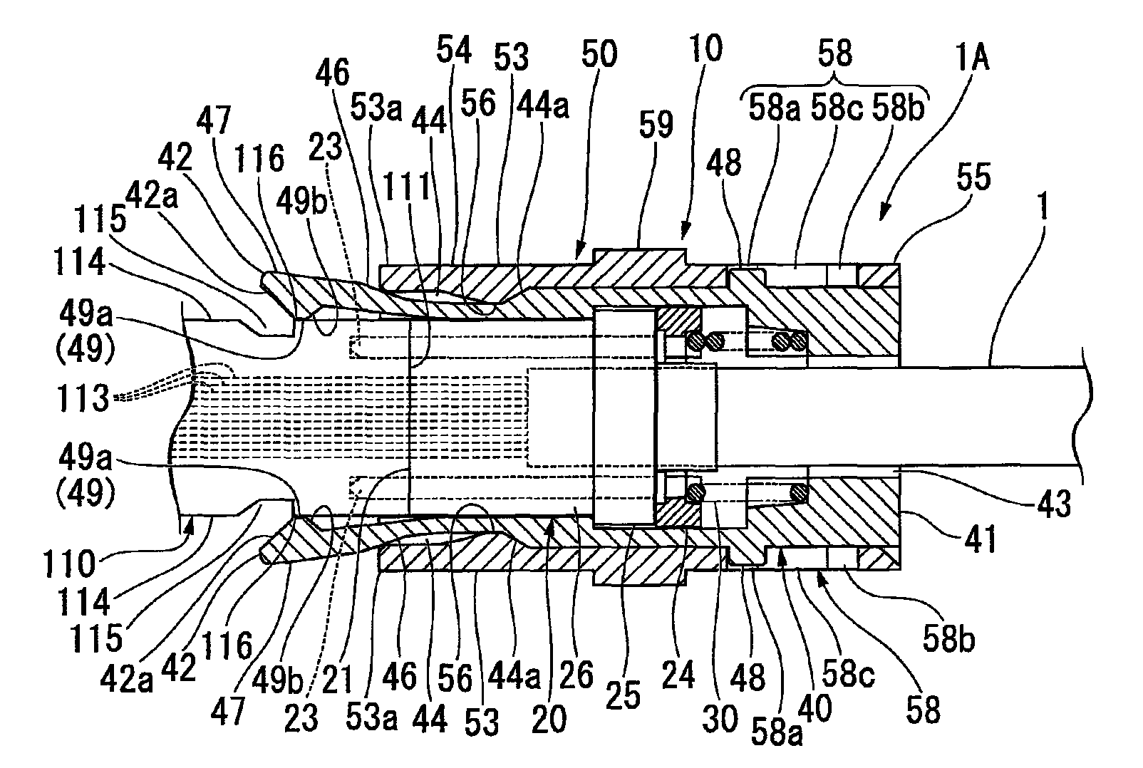
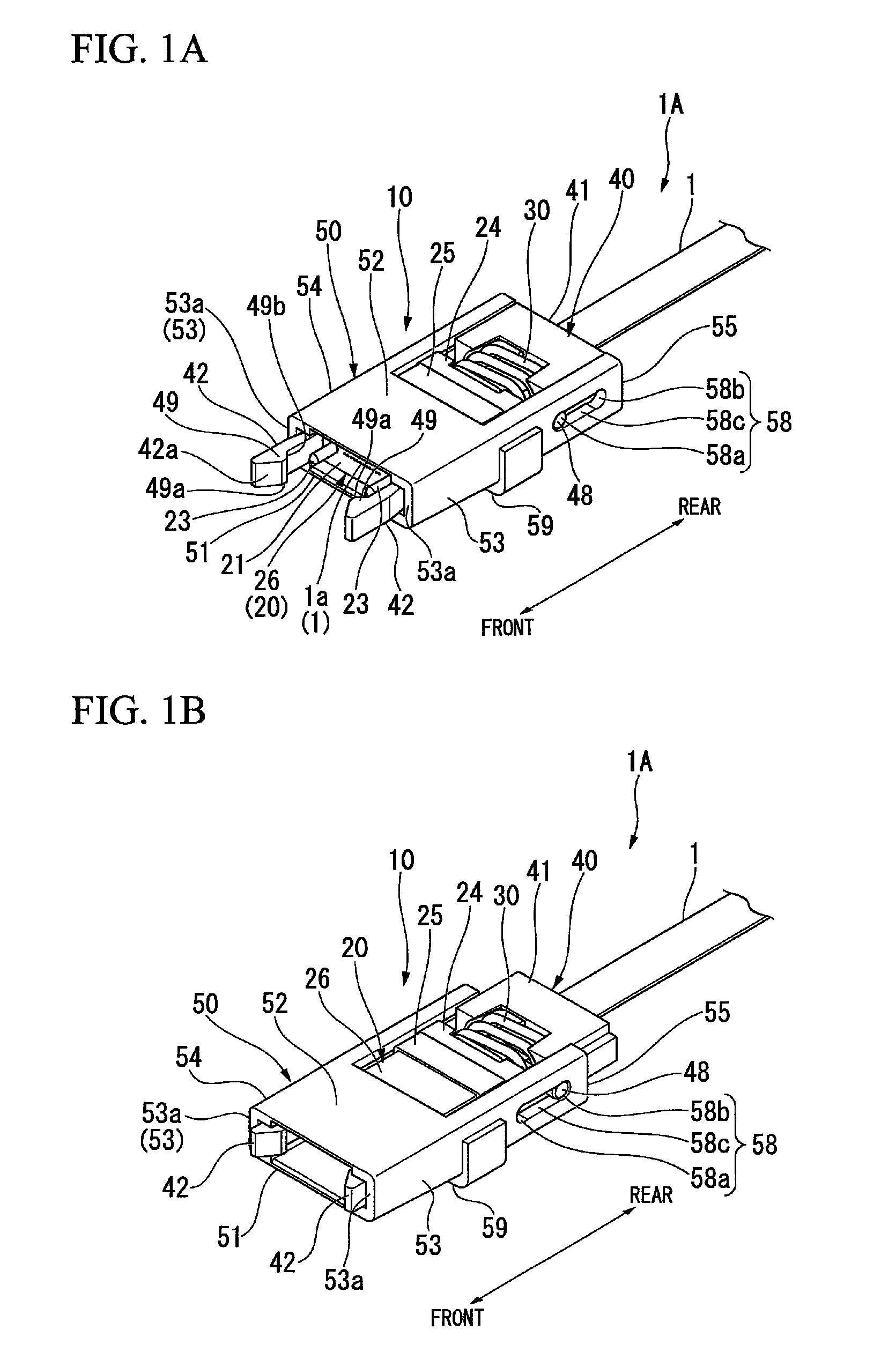
[0058]As shown in FIGS. 1A and 1B, an optical connector 10 is assembled at the tip of an optical fiber 1. In the drawings, a reference sign 1A is appended to an optical fiber having a connector in which the optical connector 10 is assembled at the tip of the optical fiber 1.

[0059]As shown in FIGS. 3 and 4, the optical connector 10 can be pushed toward a receiving-side optical connector (plug) 110, and thereby fastened and connected to the receiving-side optical connector 110 by the push-on method.

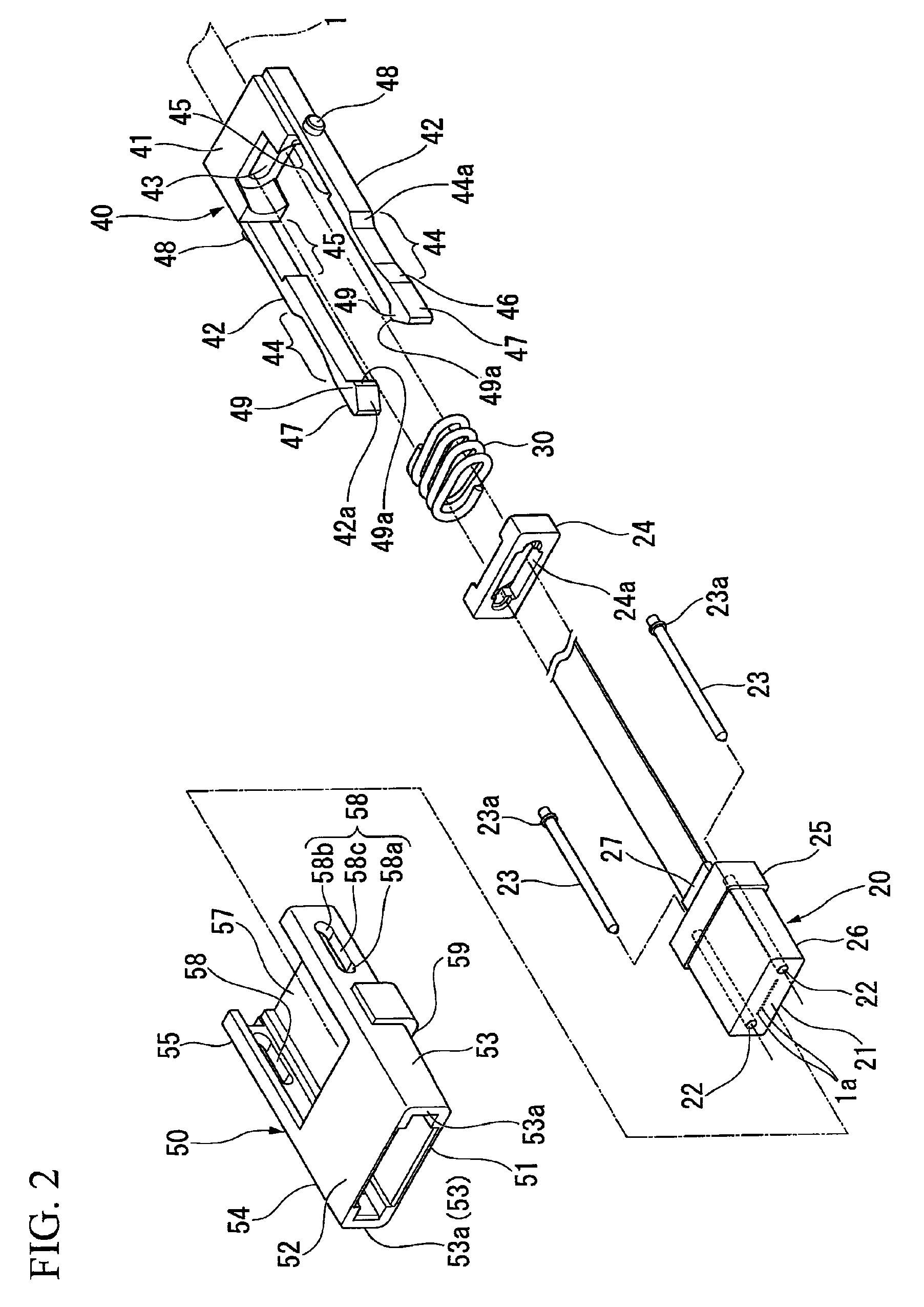
[0060]As shown by arrows in FIGS. 1A, 1B, 3, and 4, the optical connector 10 will be described, with the side where tips of a pair of elastic pieces 42 of an engaging member 40 (refer to FIG. 2) provided at the optical connector 10 are located being defined as the front and the side opposite to the front being defined as the rear....


PUM

PropertyMeasurementUnit
reaction forceaaaaaaaaaa
thicknessaaaaaaaaaa
elasticaaaaaaaaaa

Abstract

An optical connector includes: an engaging member having a pair of elastic pieces that can be engaged with locking portions on both sides of a receiving-side optical connector; and a movable tubular housing externally fitted to the engaging member, wherein the pair of elastic pieces approaches each other by an engagement with the locking portions on both sides of the receiving-side optical connector, and thereby, the housing becomes movable forward with respect to the portion of the engaging member that engages with the locking portions, and wherein an engagement state between the elastic pieces and the locking portions on both sides of the receiving-side optical connector is maintained as the pair of elastic pieces abuts an inside of the housing thereby regulating a movement in a direction of being separated from each other when the housing has moved forward with respect to the engaging member.

Description

CROSS-REFERENCE TO RELATED APPLICATION[0001]Priority is claimed on Japanese Patent Application No. 2010-173056 filed on Jul. 30, 2010, and Japanese Patent Application No. 2010-199954 filed on Sep. 7, 2010, the contents of which are incorporated herein by reference.BACKGROUND OF THE INVENTION[0002]1. Field of the Invention[0003]The present invention relates to an optical connector capable of being fastened by a push-on method, and a connector connection system using the same.[0004]2. Description of the Related Art[0005]As optical connectors, for example, there is known a plug-adapter-plug coupling-type optical connector, such as an MPO (Multi-fiber Push On)-type optical connector (an F13-type optical connector established in JIS C 5982) (for example, Japanese Standards Association, “F13-Type Multi-core Optical Connector C 5982: 1997”, JIS Handbook: Electronic Testing Method and Optoelectronics, Publishing Place: Japanese Standards Association (Foundation), Apr. 24, 1998).[0006]Meanwh...

Claims


Application Information

Patent Timeline
Patent Type & Authority Patents(United States)
IPC IPC(8): H01R13/627G02F1/1345
CPCG02B6/3897G02B6/3893G02B6/4292G02B6/3885G02B6/3821G02B6/3887G02B6/38875
Inventor KATOH, SEIJI
Owner THE FUJIKURA CABLE WORKS LTD
Why Eureka
Try Eureka