Method and apparatus for reducing motor vehicle traffic flow instabilities and increasing vehicle throughput

Inactive Publication Date: 2014-06-03
HORN BERTHOLD K P
View PDF9 Cites 11 Cited by
  • Summary
  • Abstract
  • Description
  • Claims
  • Application Information

AI Technical Summary

Problems solved by technology

Conversely, the driver may override the automated system when desired.

Method used


Image

  • Method and apparatus for reducing motor vehicle traffic flow instabilities and increasing vehicle throughput
  • Method and apparatus for reducing motor vehicle traffic flow instabilities and increasing vehicle throughput
  • Method and apparatus for reducing motor vehicle traffic flow instabilities and increasing vehicle throughput

Examples


Embodiment Construction

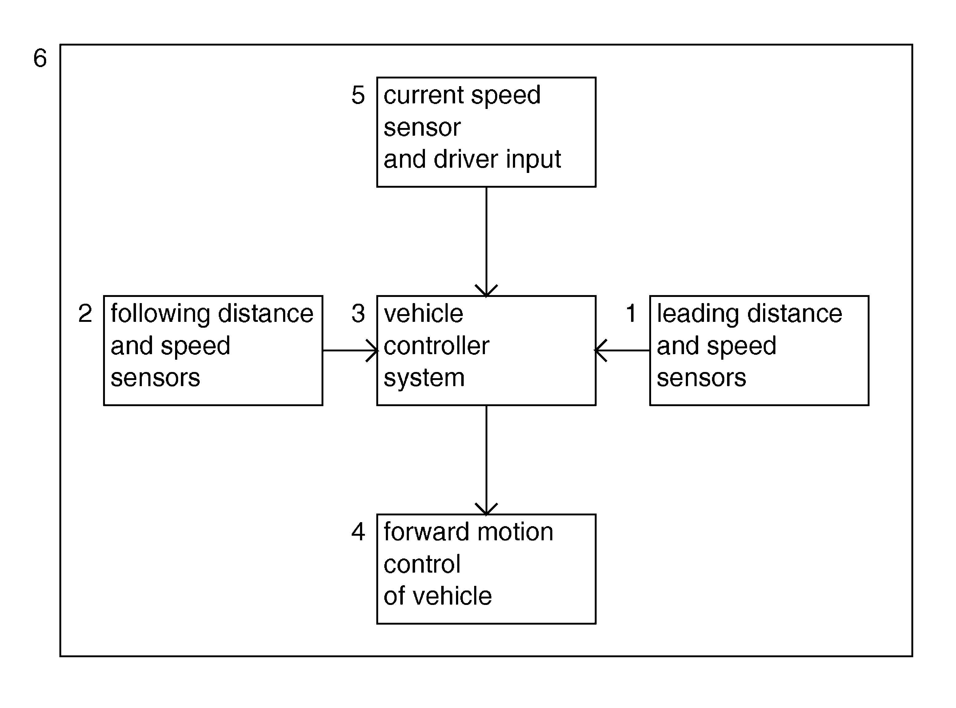
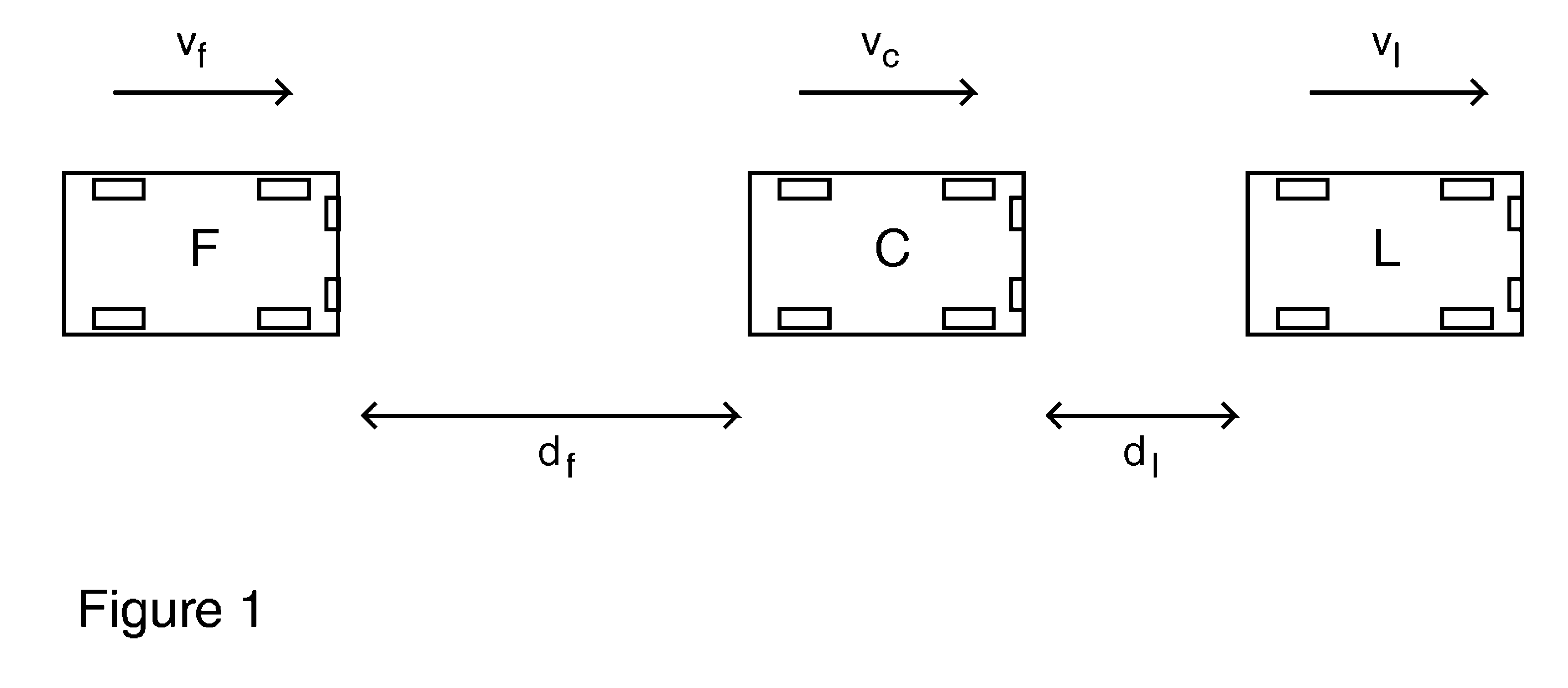
[0057]The solution to the traffic instability problem is to obtain enough total gain in each vehicle control system to prevent collisions, yet avoid a gain greater than one in any individual pathway from an input to an output. To achieve this, the control system takes into account not only the position and speed of a leading vehicle, but also the position and speed of a following vehicle. In other words, the control system is based on bilateral feedback using information that flows in both directions—from back to front and from front to back—and not just from front to back. In order to avoid ambiguity, we use the terms, “following vehicle,”“controlled vehicle,” and “leading vehicle” for three vehicles following one another as ‘F’, ‘C’, and ‘L’ do in FIG. 1. The focus is on the control system of the center or “controlled” vehicle. Of course, the leading and following vehicles may also have such control systems, but to avoid ambiguity we focus on the control system of the center or “c...


PUM


Abstract

A method and apparatus are disclosed for reducing traffic flow instabilities and increasing vehicle throughput by monitoring the distances and velocities of motor vehicles leading and following a center vehicle and controlling the velocities of the vehicles to maintain a steady relative distance between the center vehicle and the leading and following vehicles. Using distance and speed information derived from both leading and following vehicles reduces the loop gain of feedback needed below one (1) and diminishes traffic instabilities caused by “car following.”

Description

CROSS-REFERENCE TO RELATED APPLICATION[0001]This application claims the benefit of U.S. Patent Application No. 61 / 253,611, filed on Oct. 21, 2009, the contents of which is incorporated by reference herein in its entirety.BACKGROUND[0002]Traffic flow instabilities include slowdowns, back-ups, and alternating waves of stop-and-go driving, which often appear to occur for no obvious reason such as an accident or road construction work. These periodic and often rapid variations in speed and traffic density reduce overall traffic throughput on highways and increase the danger of collisions, cause higher fuel consumption and wear and tear on vehicles, faster abrasion of roadways, and waste the time and fray the nerves of motorists.[0003]Traffic flow instabilities are best understood in light of the relationship between vehicle density and speed. Vehicle density is the number of vehicles in a unit length of a roadway and depends on the average length of such vehicles and the distance betwee...

Claims


Application Information

Patent Timeline
Patent Type & Authority Patents(United States)
IPC IPC(8): G01C23/00B60W30/16G01C22/00
CPCB60W2520/10B60W2550/408B60W2550/308B60W2050/008B60W2720/106B60W30/16B60W2556/65B60W2554/801B60W2050/0075
Inventor HORN, BERTHOLD, K., P.
Owner HORN BERTHOLD K P
Why Eureka
Try Eureka