Apparatus for the production of an aircraft fuselage shell consisting of a fibre composite

a technology of fibre composite and aircraft fuselage, which is applied in the direction of ammunition loading, efficient propulsion technologies, other domestic articles, etc., can solve the problems of increasing production effort, difficult to produce, and difficult to handle the long formed parts, and achieves the effect of simple and precise manner

Active Publication Date: 2014-06-10
AIRBUS OPERATIONS GMBH
View PDF22 Cites 7 Cited by
  • Summary
  • Abstract
  • Description
  • Claims
  • Application Information

AI Technical Summary

Benefits of technology

[0011]An aspect of the present invention provides an apparatus for the production of a fuselage shell consisting of a fibre composite and equipped with hard stringers, the components of which can be produced in a simple and precise manner, and which allows a reproducible high-precision serial production of stringer-reinforced fuselage shells.
[0014]Therefore, a major advantage of the solution according to an aspect of the invention is the position of the stringers may be adjusted individually in order to react, for example, to thermal or chemical shrinking effects or to device tolerances. In addition, the production tolerance of the device can be expanded, which allows a more simple production. By means of the solution according to an aspect of the invention, a directed guiding of the stringer during the transfer process towards the LABU and thus in the direction of the outer shell is obtained. It is not necessary any more to use large and massive form parts, but only relatively small positioning inserts, which, ideally, can be designed as identical parts. At the same time, in doing so, a much smaller cleaning effort during operation is obtained in comparison with previously known solutions.
[0018]By insertion of the main section into the longitudinal groove, the T stringer is positioned correctly in a simple manner. According to a measure improving the co-action of the T stringer and the longitudinal groove of the formed part it is proposed to arrange an additional clamping means between the two, which serves a connection of the T stringer in the longitudinal groove in a force-locking manner. Said clamping means is, preferably, embodied as an elastic mat, which may comprise a small-pore elastomer foam material or similar, which provides, besides the desired clamping effect according to an additional advantage, also a compensation of tolerance between the geometries of the T stringer and of the device.
[0019]The adjusters for adjusting the formed part in the transverse direction relative to the mounting groove can be embodied in a simple manner as adjusting plates arranged on both sides of the groove flanks. By selecting adjusting plates of a suitable thickness and by arranging them between the mounting groove and the formed part, any conceivable positions of the formed part can be realized in a simple manner in the transverse direction within the mounting groove. As an alternative, however, it is also conceivable to embody the adjusters as bushing units / guiding units arranged on both sides of the groove flanks or similar.

Problems solved by technology

By means of said continuous formed parts for the positioning of the T stringers relative to the mounting surface, a precise production of the reinforced fuselage shell can be obtained, however, the elongated formed parts are not easy to handle and difficult to produce.
In addition, before every application release agents need to be applied on the elongated formed parts, and they must be cleaned as well, which requires a lot of work.
This, additionally, increases the production effort.
In addition, while co-acting with the LABU, it is not possible to actively guide the stringers during the transfer process.

Method used


Image

  • Apparatus for the production of an aircraft fuselage shell consisting of a fibre composite
  • Apparatus for the production of an aircraft fuselage shell consisting of a fibre composite
  • Apparatus for the production of an aircraft fuselage shell consisting of a fibre composite

Examples


Embodiment Construction

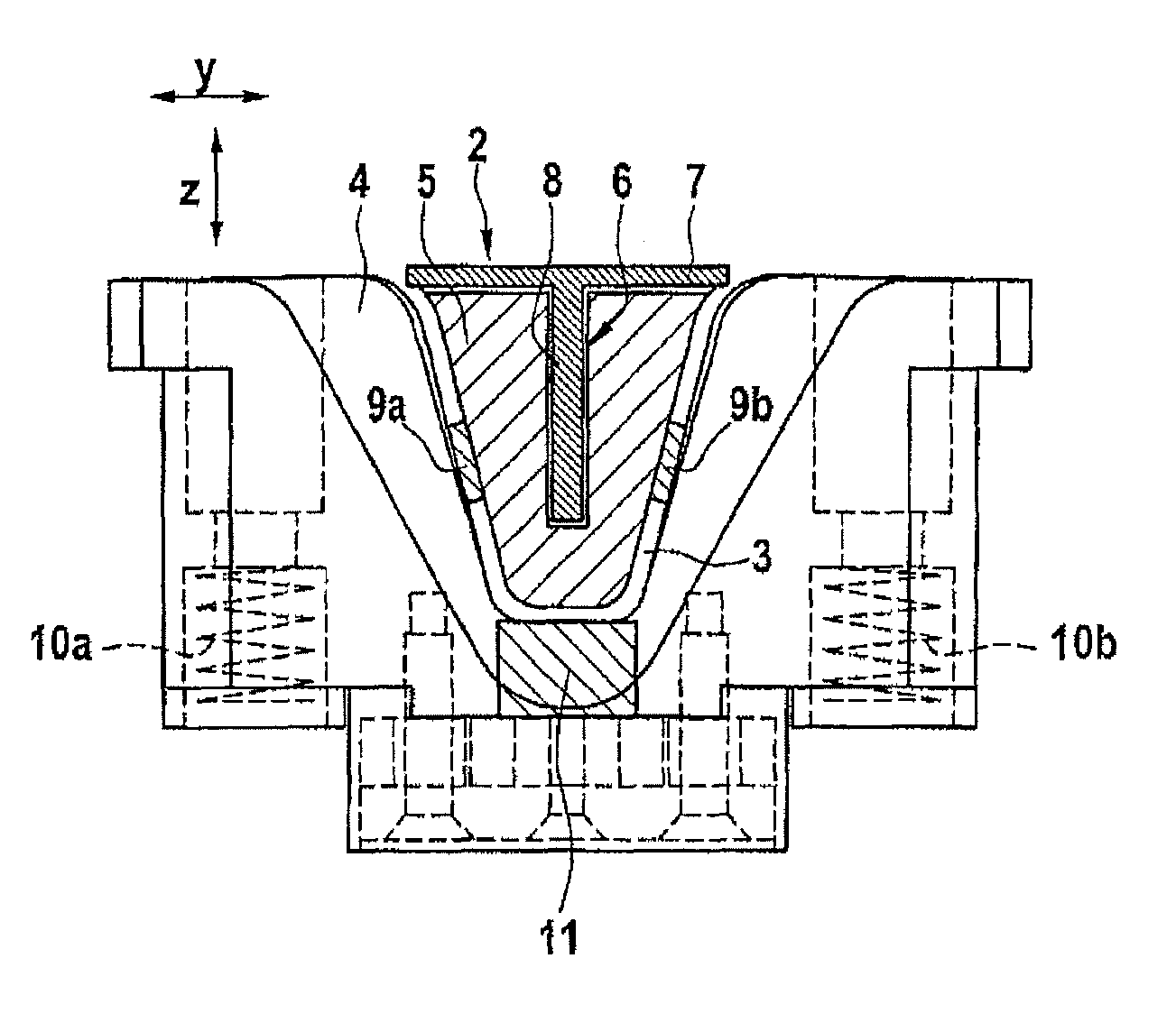
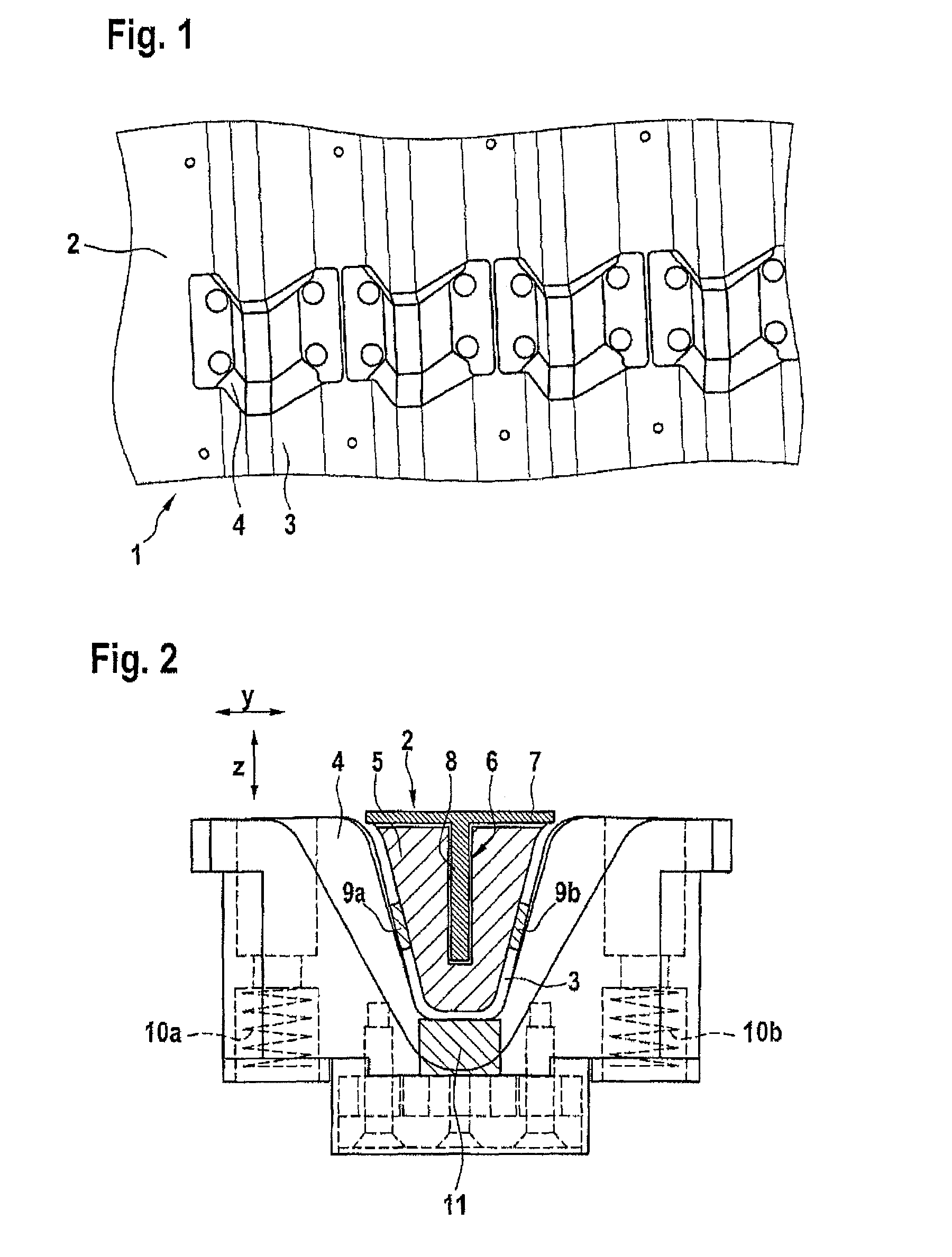
[0029]According to FIG. 1, the apparatus for the production of the fuselage shells, which are not further depicted, for an aircraft essentially comprises a main frame (1), which is arranged below a mounting surface (2) for forming a supporting substructure. The outwardly curved mounting surface (2) serves the purpose of positive mounting and comprises several mounting grooves (3) running parallel for receiving formed parts—not depicted here—for the insertion of stringers. At the place where the formed parts are inserted into the mounting groove (3) there are positioning inserts (4), which can be raised by means of lifters in order to later raise the stringers inserted herein in direction of a laminating adhesive bonding unit (LABU) brought over the mounting surface (2).

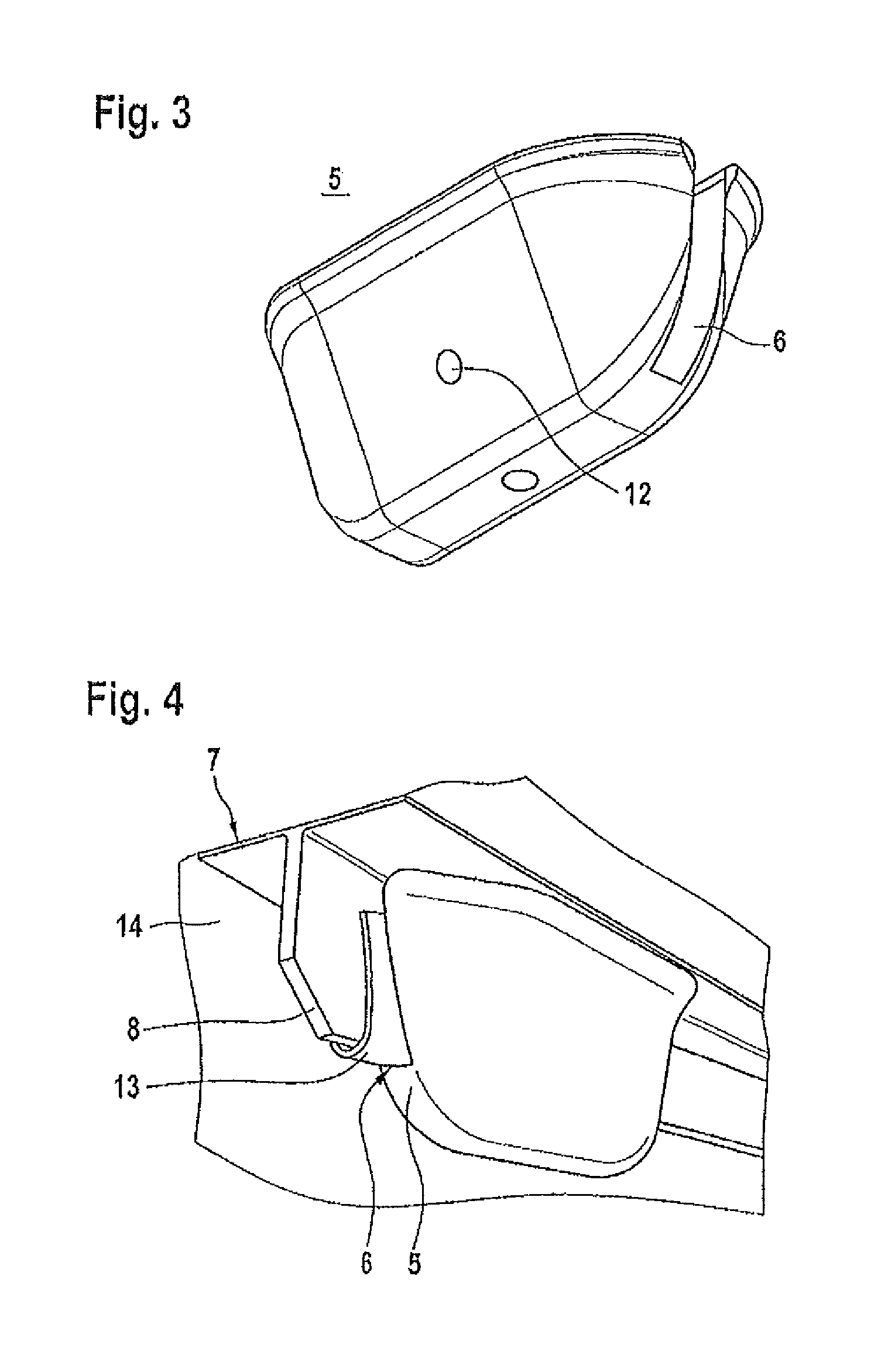
[0030]According to FIG. 2), a short formed part (5) (exemplary depiction) is inserted into the mounting groove (3) formed by the positioning insert (4). Along the longitudinal extension of each mounting groove (3) of ...


PUM

PropertyMeasurementUnit
lengthaaaaaaaaaa
elasticaaaaaaaaaa
pressureaaaaaaaaaa

Abstract

An apparatus for the production of a fuselage shell for an aircraft made of fiber composite, which is to be equipped with a plurality of stringers disposed spaced apart for reinforcement, comprising a main frame to form a supporting substructure having an outwardly curved mounting surface for positive mounting, having longitudinal mounting grooves for receiving of formed parts for deformably positioning the stringers relative to the mounting surface, wherein a plurality of short formed parts spaced apart from each other are disposed in each mounting groove, and which are adjustable relative to the corresponding mounting groove in the transverse direction (Y) by means of adjusters, and which can be raised in the vertical direction (Z) by means of lifters for guiding the stringers in the direction of a laminating adhesive bonding unit brought over the mounting surface.

Description

CROSS-REFERENCE TO RELATED APPLICATIONS[0001]The present application is a continuation of International Application No. PCT / EP2010 / 069056, filed Dec. 7, 2010, published in German, which claims priority from German Application No. 10 2009 059 720.4 filed Dec. 18, 2009, and which claims the benefit of the filing date of U.S. Provisional Patent Application No. 61 / 287,855 filed on Dec. 18, 2009, the disclosures of which are hereby incorporated herein by reference.AREA OF THE INVENTION[0002]The invention relates to an apparatus for the production of a fuselage shell consisting of a fibre composite for an aircraft, which is to be equipped with a plurality of stringers disposed spaced apart from one another for reinforcement, comprising a main frame for forming a supporting substructure having an outwardly curved mounting surface for positive mounting, having longitudinal mounting grooves for receiving formed parts in a form-fit manner for deformably positioning the stringers relative to t...

Claims


Application Information

Patent Timeline
Patent Type & Authority Patents(United States)
IPC IPC(8): B29C65/78
CPCY02T50/433B29C70/541Y02T50/43B29L2031/3082B29D99/0014Y10T156/1759Y10T156/1754Y02T50/40
Inventor BARLAG, CARSTENPIEPENBROCK, JOACHIM
Owner AIRBUS OPERATIONS GMBH
Why Eureka
Try Eureka