Data storage system and method for monitoring and controlling the power budget in a drive enclosure housing data storage devices

a data storage system and power budget technology, applied in the field of data storage systems, can solve the problems of increased drive failure rate, excessive operation cost, and sometimes excessive power consumption of drives

Active Publication Date: 2014-06-10
DATADIRECT NETWORKS
View PDF14 Cites 60 Cited by
  • Summary
  • Abstract
  • Description
  • Claims
  • Application Information

AI Technical Summary

Benefits of technology

[0023]It is therefore an object of the present invention to provide an efficient power management mechanism for a data storage system implemented in a drive enclosure through real-time monitoring and control of power consumption of the storage devices exclusively within the drive enclosure.
[0024]It is another object of the present invention to provide a data storage system implemented in a drive enclosure where a plurality of client / compute nodes access the interposers of target storage devices directly through the SAS expander of the drive enclosure. This avoids the data passage through SAS ports, CPU and the DRAM of the drive enclosure, thereby eliminating the need for buffering the IO data in the drive enclosure.

Problems solved by technology

Complex data storage systems with fully populated drive enclosures housing dynamic massive array of drives sometimes experience periods of unwanted excessive power consumption and elevated heat generation.
Heat generated as a result of a large power consumption may cause increased drive failure rates, while excessive power consumption may lead to excessive operation costs and unwanted overload.
In order to prevent severe crashes due to excessive heating, a sufficient cooling regime has to be provided within the data storage system resulting in high electrical expenses driving up the operation costs.
“Green” drives have been used in contemporary storage systems that consume a moderate amount of power due to their relatively slow rotation, thus requiring lesser cooling.
Unfortunately, high power consumption during “cold” start of the system due to a large amount of current drawn by the drives for spinning up results in elevated heat generation.
Alternatively, costly hardware is required which involves SAS (Serial Attached SCSI) interface and DRAM (Dynamic Random-Access Memory) to buffer the host data (I / O requests) before transferring to the drives by the controller.
The task becomes even more challenging in case of Virtual Machine environment where the information cannot be shared between different applications running on different guest operating systems where different controllers try to access the same storage device.
In this situation, it is extremely difficult to coordinate information about the target storage device and this results in less than optimal power management.
Unfortunately, in this type of arrangement, the data (IO) transfer path through the SAS port 22, CPU 28, and the DRAM 30 creates a “bottle neck” which may undesirably slow the data tunneling through the system and may require the DRAM to buffer all of the IO in the drive enclosure.
This arrangement is defective from an efficiency standpoint.

Method used


Image

  • Data storage system and method for monitoring and controlling the power budget in a drive enclosure housing data storage devices
  • Data storage system and method for monitoring and controlling the power budget in a drive enclosure housing data storage devices
  • Data storage system and method for monitoring and controlling the power budget in a drive enclosure housing data storage devices

Examples


Embodiment Construction

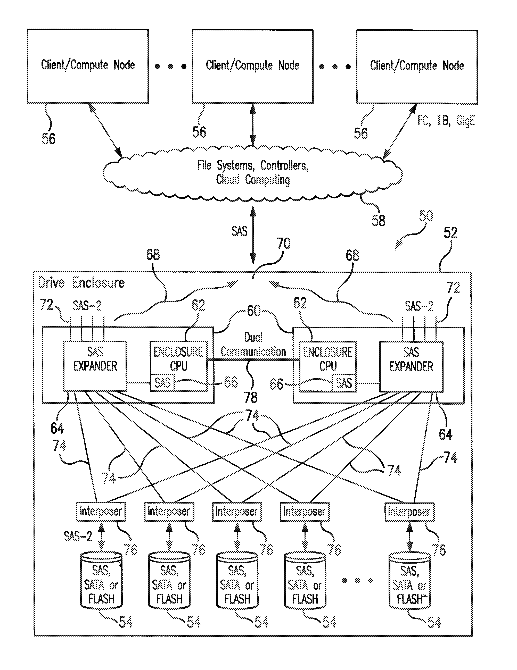
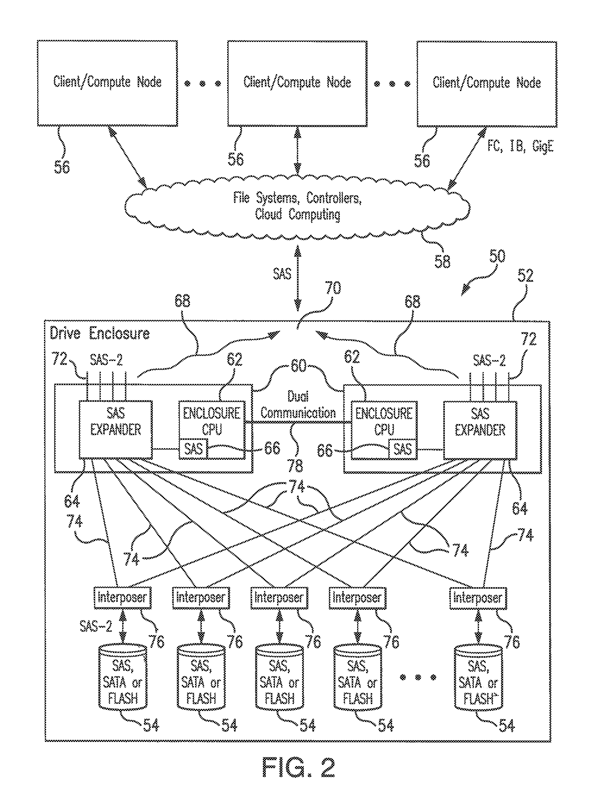
[0088]Referring to FIG. 2, system 50 of the present invention constitutes a data storage system implemented in a drive enclosure 52 which incorporates a plurality of data storage devices 54 which may be in the form of disk drives as well as flash drives. The drive enclosure 52 is built with components for supporting IO operation between client / compute nodes 56 and target storage devices 54 through the computing cloud 58.

[0089]As shown in FIG. 2, the drive enclosure 52 is built with redundant (for example two) IO modules 60. Each IO module 60 includes an enclosure CPU 62 connected to the SAS expander 64 over the SAS PHY interface 66. In the present system 50, all IO transmissions are carried out directly to the target drives 54 without passing through the DRAM of the enclosure CPU. Specifically, data 68 (for example, IO request) received from the client / compute nodes 56 at the SAS port 70 of the drive enclosure 52 is connected to the IO module 60 through SAS-2 interface 72 to the SAS...


PUM


Abstract

A control processor manages the power budget in a drive enclosure and is within the drive enclosure which monitors in real time a redundantly configured power supply unit, drives, interposers, and temperature sensors, and determines the power settings for each drive to avoid overload and overheating in the system. The control processor dynamically adjusts the mode of operation as needed during operation through the SAS interposer. A localized monitoring and control mechanism eliminates the need for extraneous coordination of information across various entities that access the storage. Data tunneling takes place directly between the compute nodes and target drives through the SAS expander and interposer, and does not need buffering the pending IO requests in the DRAM.

Description

FIELD OF THE INVENTION[0001]The present invention is directed to a data storage system provided with a power consumption monitoring and control mechanism to efficiently address power budget management requirements.[0002]In general, the present invention is directed to a data storage system implemented with a plurality of data storage devices incorporated in a drive enclosure which are accessed by compute nodes for data IO (Input-Output) activity. The power budget of the drive enclosure is controlled by a control processor operating within the drive enclosure which in real-time monitors the components of the drive enclosure and dynamically adjusts the power settings of the data storage devices.[0003]In particular, the present invention is directed to a data storage system where the power budget of a drive enclosure is controlled internally without the need for coordination with compute nodes activity which access the data storage system with IO requests, where the control processor i...

Claims


Application Information

Patent Timeline
Patent Type & Authority Patents(United States)
IPC IPC(8): G06F1/26
CPCG06F1/26G06F1/3268Y02B60/1246Y02D10/00
Inventor PISZCZEK, MICHAEL J.MISHRA, MANJARIHARKER, WILLIAM JOSEPHPERSHALL, ANDREWFELLINGER, DAVID F.
Owner DATADIRECT NETWORKS
Why Eureka
Try Eureka