Hydraulic valve for an oscillating motor adjuster

a technology of oscillating motor and hydraulic valve, which is applied in the direction of valve arrangement, non-mechanical valve, thin material handling, etc., can solve the problems of hydraulic valve stress, and achieve the effects of accurate design, cost-effectiveness, and large play in the configuration

Active Publication Date: 2014-06-17
HILITE GERMANY
View PDF184 Cites 5 Cited by
  • Summary
  • Abstract
  • Description
  • Claims
  • Application Information

AI Technical Summary

Benefits of technology

[0019]According to one advantage of the invention, the hydraulic valve of the oscillating motor adjuster is designed as a central valve. Such a central valve has advantages relative to structural space. In addition to central valves, there are also decentralized or external hydraulic valves for actuating the oscillating motor adjuster. In the case of the external hydraulic valve, the hydraulic channels for the camshaft adjustment run from the oscillating-motor camshaft adjuster to a separate timing gear cover with the hydraulic valve screwed therein or, alternatively, to the cylinder head having the hydraulic valve screwed therein. Conduction losses accompany the hydraulic lines from the oscillating motor adjuster to the external hydraulic valve. The controls from the external hydraulic valve are also not as dynamically reactive as in the case of the central valve. The hydraulic central valve is also radially disposed within the rotor hub of the oscillating motor adjuster.
[0020]If the hydraulic valve is designed as a central valve, then the axial fixation of the hydraulic valve opposite the camshaft can be designed as separate from the axial bracing of the rotor against the camshaft. In comparison to central valves, which are also central screws, this makes possible a large play in the configuration without taking into consideration structural mechanical problems. Therefore, high-strength material need not be used. For example, light metal, in particular aluminum, can be applied as the material. Also, hydraulic control edges can be accurately designed on the central valve. Sealing rings, in particular O rings, for bridging the gap can be dispensed with. Since a large screw head on the central valve is not necessary, the central valve can be manufactured with a relatively uniform outer diameter, so that only a relatively small amount of material needs to be used, which makes the central valve cost-effective. In order to join the rotor to the camshaft in a torsionally rigid manner, the rotor can be welded on or can be pressed on with a micro-serration. In one possible configuration, it is also possible to clamp the rotor axially with a nut against a shoulder on the camshaft. The nut can thus be screwed onto an outer thread at the end of the camshaft. The nut keeps the central valve free from stresses.
[0021]In a further possible configuration, the piston is completely pressure-equilibrated.
[0022]The camshaft can be designed in particular as a built-in camshaft. Such built-in camshafts comprise a hollow tube, onto which the cams are shrunk-fit. These built-in camshafts are cost-effective and lightweight.
[0023]In one example embodiment of the invention, the hydraulic valve is inserted as a central valve inside the rotor. Thus, since the paths between the hydraulic valve and the pressure chambers are very short, such a hydraulic valve has advantages in its effectiveness and dynamics. Advantages relative to structural space are also achieved. If the central valve is designed as a central screw, it must be dimensioned appropriately, in order to take up the stresses for clamping the rotor. With the present invention, the central valve may also be inserted inside the rotor if the camshaft lies in between as a hollow shaft.
[0024]In a further example embodiment of the invention, recesses that have several functions for conducting the hydraulic fluid are provided in the displaceable piston. The recesses conduct the hydraulic fluid from a supply channel inside the piston into the working chambers. These recesses also conduct pressure peaks that result from camshaft alternating torques from the working chambers into the supply channel. These recesses, however, are not provided for discharge of hydraulic fluid to the tank outlet. These recesses may have annular grooves, for example, so that the piston does not need to be oriented at an angle opposite the borehole or the bush. Such an annular groove for the distribution of the hydraulic fluid over the periphery, however, can also be worked into the inside wall of the bush.

Problems solved by technology

Thus, as a disadvantage, stresses occur in the hydraulic valve.

Method used


Image

  • Hydraulic valve for an oscillating motor adjuster
  • Hydraulic valve for an oscillating motor adjuster
  • Hydraulic valve for an oscillating motor adjuster

Examples


Embodiment Construction

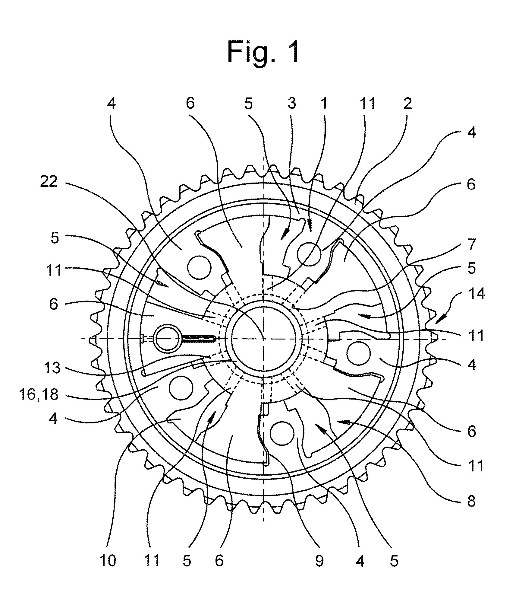
[0031]The angular position of a camshaft 18 can be continuously changed relative to a drive wheel 2 with an oscillating motor adjuster 14 according to FIG. 1 during the operation of an internal combustion engine. By rotating camshaft 18, the opening and closing time points of the gas exchange valves are shifted so that the internal combustion engine offers its optimal performance at the speed involved. The oscillating motor adjuster 14 has a cylindrical stator 1, which is joined in a torsionally rigid manner to drive wheel 2. In the example embodiment shown in FIG. 1, drive wheel 2 is a chain wheel, by means of which a chain, which is not shown in more detail, is guided. Drive wheel 2, however, may also be a toothed belt gear by means of which a drive belt is guided as a drive element. Stator 1 is drive-connected to the crankshaft by means of this drive element and drive wheel 2.

[0032]Stator 1 comprises a cylindrical stator base 3, on the inner side of which webs 4 protrude radially...


PUM


Abstract

The invention relates to a hydraulic valve for an oscillating motor adjuster that utilizes camshaft alternating torques by means of non-return valves for more rapid adjustment. The non-return valve that is not used for the respective rotation is additionally closed by means of the piston of the hydraulic valve.

Description

[0001]This application claims the benefit of German patent application no. DE 10 2010 061 337.1 filed on Dec. 20, 2010, which is incorporated herein and made a part hereof by reference for all purposes.BACKGROUND OF THE INVENTION[0002]The invention relates to a hydraulic valve for an oscillating motor adjuster that utilizes camshaft alternating torques by means of non-return valves for more rapid adjustment.[0003]An oscillating motor adjuster having a hydraulic valve with which camshaft alternating torques can be utilized for more rapid adjustment is already known from DE 10 2006 012 733 B4 and DE 10 2006 012 775 B4. For this purpose, pressure peaks caused by camshaft alternating torques are conducted from each of the pressure chambers of the oscillating motor adjuster to be discharged via a non-return valve into the flow of the oil pump. Thus, additional volume is provided for the pressure chamber to be filled, in addition to the normal flow volume of the oil pump. In order to make...

Claims


Application Information

Patent Timeline
Patent Type & Authority Patents(United States)
IPC IPC(8): F01L1/344F01L1/34
CPCF01L1/344F01L1/34409F01L1/3442Y10T137/8671
Inventor SCHULZE, WOLF-DIETMARSELKE, ANDRE
Owner HILITE GERMANY
Why Eureka
Try Eureka