
Exhaust treatment device for a diesel engine

a treatment device and diesel engine technology, applied in auxillary pretreatment, electrical control, separation processes, etc., can solve the problems long cancel period, and dpf may be thermally damaged, so as to prevent the cancel period from becoming, prevent the effect of thermal damage to dpf 1 when regenerating dp

Active Publication Date: 2014-06-24
KUBOTA LTD
View PDF13 Cites 3 Cited by
  • Summary
  • Abstract
  • Description
  • Claims
  • Application Information

AI Technical Summary

Benefits of technology

This invention aims to prevent thermal damage to a DPF (Diesel Particulate Filter) during regeneration. By allowing the automatic DPF regeneration processing to start sooner, the invention reduces the duration of the cancellation period and prevents PM (particulate matter) from accumulating excessively on the DPF. This reduces the risk of thermal damage and ensures safe regeneration of the DPF. Additionally, the invention also integrates a notification system to alert the operator about the exceeded cancel state permission, giving them time to take necessary steps to prevent PM accumulation. Overall, this invention prevents thermal damage to the DPF and ensures safe and efficient regeneration of the filter.

Problems solved by technology

The DPF may be thermally damaged when the DPF is regenerated.
A cancel period becomes long because the cancel state of the automatic DPF regeneration processing cannot be freely released, and the DPF may be thermally damaged because PM excessively accumulated during cancel is combusted rapidly and strongly when the DPF is regenerated and thus the DPF is overheated.

Method used


Image

  • Exhaust treatment device for a diesel engine
  • Exhaust treatment device for a diesel engine
  • Exhaust treatment device for a diesel engine

Examples


Embodiment Construction

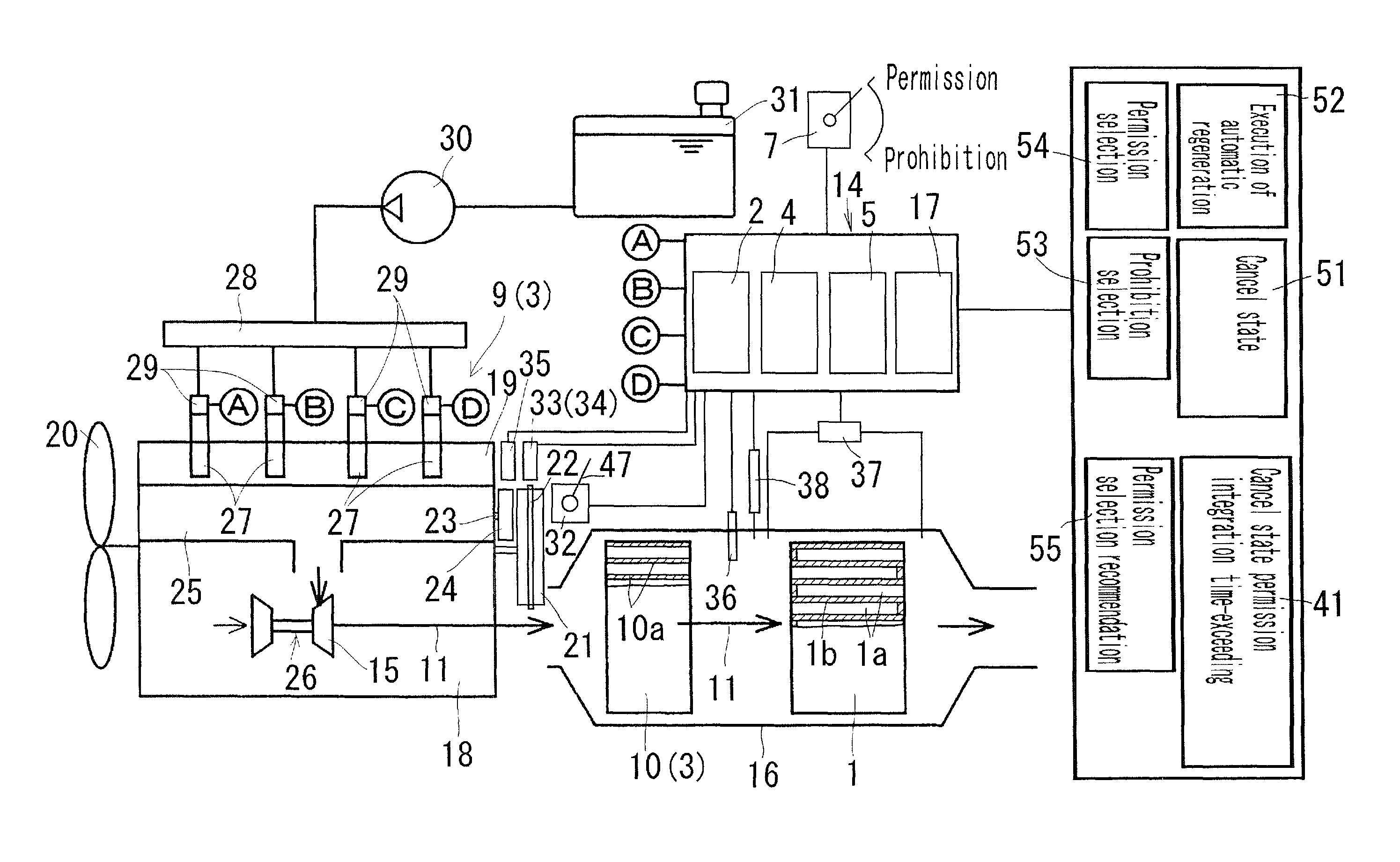
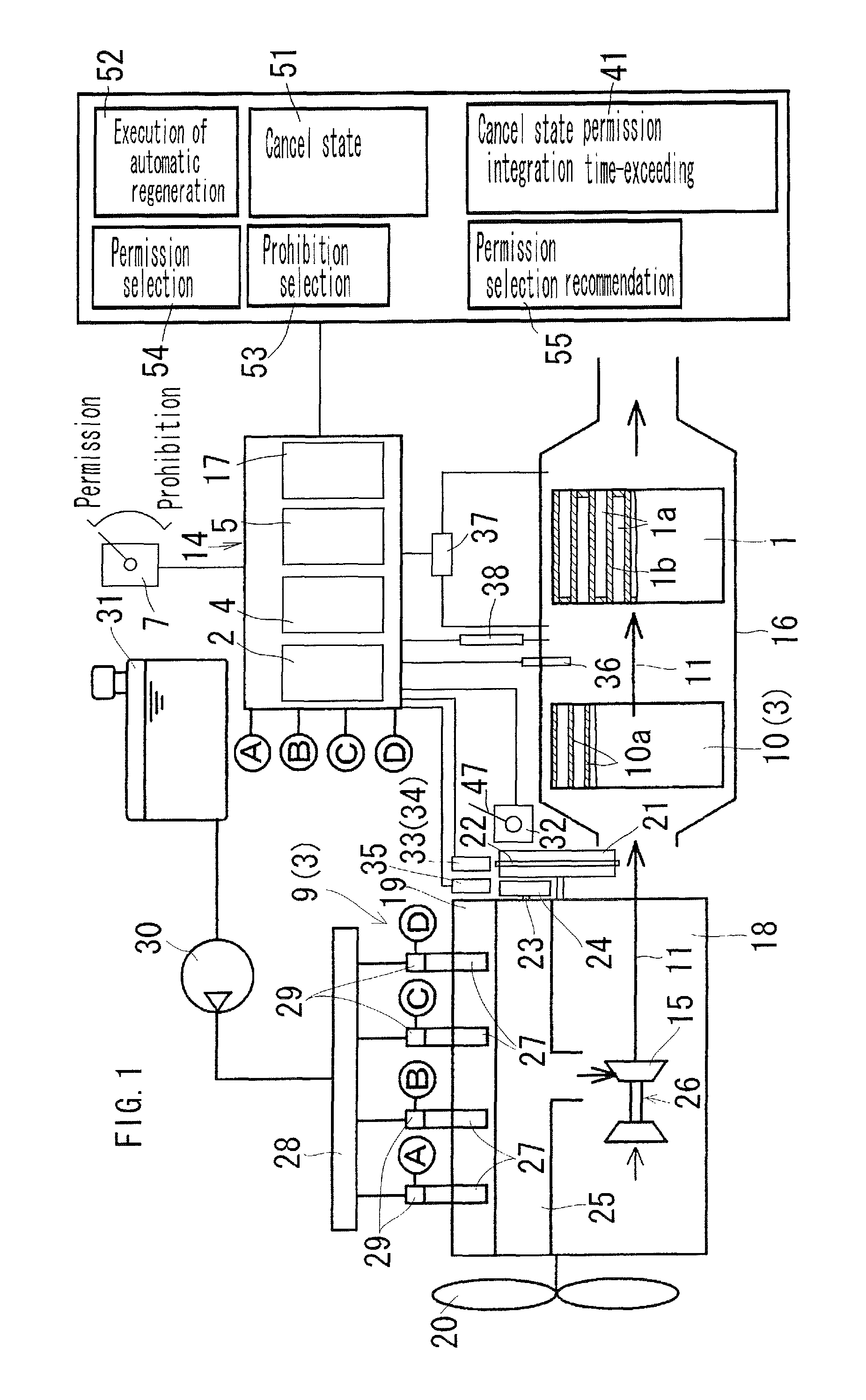
[0057]FIGS. 1 to 4 are diagrams illustrating an exhaust treatment device for a diesel engine relating to embodiments of the present invention. In the present embodiment, a common rail type multi-cylinder diesel engine equipped with the exhaust treatment device is described below.

[0058]An outline of the diesel engine shown in FIG. 1 is described below.

[0059]A cylinder head 19 is assembled over the cylinder block 18, an engine cooling fan 20 is disposed at the fore part of the cylinder block 18, a fly wheel 21 is disposed at the rear part of the cylinder block 18, and a rotor plate 22 is mounted on the fly wheel 21. Furthermore, a sensor plate 24 mounted on a valve-driven cam shaft 23 is disposed at the rear part of the cylinder block 18. An exhaust manifold 25 is disposed on one side of the cylinder head 19, and a supercharger 26 communicates with the exhaust manifold 25. A DPF accommodating casing 16 in which a DPF 1 is accommodated is disposed in the lower stream of the turbine 15 ...


PUM

PropertyMeasurementUnit
state integration time computationaaaaaaaaaa
cancel state integration timeaaaaaaaaaa
temperatureaaaaaaaaaa

Abstract

The disclosed exhaust treatment device for a diesel engine can prevent heat damage to a DPF when regenerating said DPF. If a selection device (7), which selects whether to allow or prohibit an automatic DPF regeneration process, is set to prohibit the automatic DPF regeneration process, a DPF regeneration control device (4) is made able to start a process to cancel execution of the automatic DPF regeneration process. If the selection device (7) is set to allow the automatic DPF regeneration process, the DPF regeneration control device (4) retracts the cancellation of the automatic DPF regeneration process, allowing execution of the previously-cancelled automatic DPF regeneration process to begin.

Description

CROSS-REFERENCE TO RELATED APPLICATION[0001]This application is a Section 371 of International Application No. PCT / JP2011 / 056178, filed Mar. 16, 2011, which was published in the Japanese language on Sep. 29, 2011, under International Publication No. WO 2011 / 118464 A1, and the disclosure of which is incorporated herein by reference.TECHNICAL FIELD[0002]The present invention relates to an exhaust treatment device for a diesel engine and, more particularly, to an exhaust treatment device for a diesel engine which is capable of preventing thermal damage to a DPF when regenerating the DPF.[0003]From among terms in the present invention, a DPF is an abbreviation of a Diesel Particulate Filter, a PM is an abbreviation of Particulate Material included in an exhaust gas, and a DOC is an abbreviation of a diesel oxidation catalyst.BACKGROUND ART[0004]Conventionally, a DPF regeneration control device starts the execution of automatic DPF regeneration processing based on the fact that the accum...

Claims


Application Information

Patent Timeline
Patent Type & Authority Patents(United States)
IPC IPC(8): B01D39/14B01D24/00B01D39/06B01D39/20B01D50/00
CPCF02D41/22F01N3/035F02D41/029F02D41/0245F02N11/08F02N11/0814F02D41/405F02D41/025Y02T10/12Y02T10/40
Inventor FUJII, YASUOFUJIWARA, MASANORIINOUE, KATSUSHIISHII, YUUKIMITAMURA, KENTAEGUCHI, NORIYOSHILEE, YONGCHOLNINOMIYA, TOMOHIRO
Owner KUBOTA LTD
Learn More