
Methods for continuously moving a fluid dispenser while dispensing amounts of a fluid material

a technology of fluid dispenser and movement, applied in the direction of liquid/fluent solid measurement, liquid transfer device, packaging, etc., can solve the problems of vibration in the jetting dispenser, the movement is not continuous, etc., and achieve the effect of reducing spatial errors

Inactive Publication Date: 2014-07-01
NORDSON CORP
View PDF28 Cites 5 Cited by
  • Summary
  • Abstract
  • Description
  • Claims
  • Application Information

AI Technical Summary

Benefits of technology

The patent text describes a method for dispensing fluid material onto a substrate using a dispenser that moves continuously through a constant motion trajectory. The method involves initiating the dispensing of amounts of material at predetermined locations in advance of the dispenser's arrival at those locations. This allows for precise and accurate placement of the material on the substrate. The technique can be controlled and synchronized with the dispenser's movement to optimize the process. The technical effect of this invention is to provide a reliable and efficient way to dispense fluid materials onto a substrate, leading to improved manufacturing efficiency and accuracy.

Problems solved by technology

However, the motion is not continuous.
In that specific application, the stop and start between consecutive line segments lengthens the dispensing time and, furthermore, causes vibration in the jetting dispenser.

Method used


Image

  • Methods for continuously moving a fluid dispenser while dispensing amounts of a fluid material
  • Methods for continuously moving a fluid dispenser while dispensing amounts of a fluid material
  • Methods for continuously moving a fluid dispenser while dispensing amounts of a fluid material

Examples


Embodiment Construction

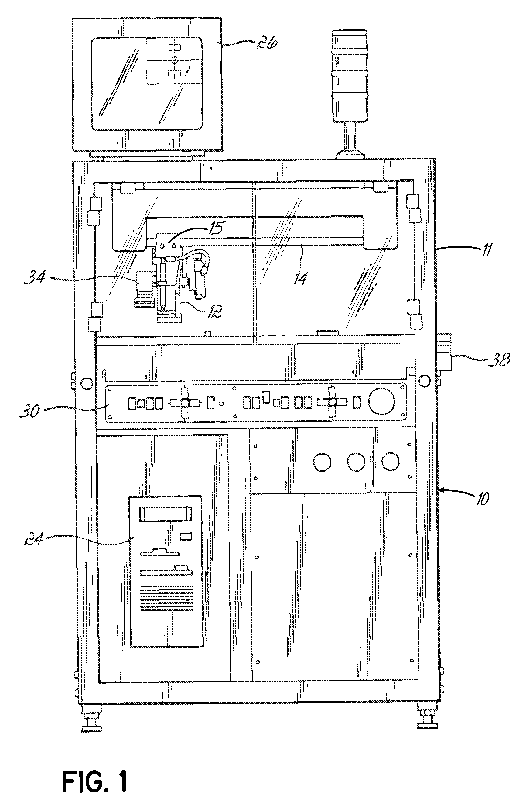
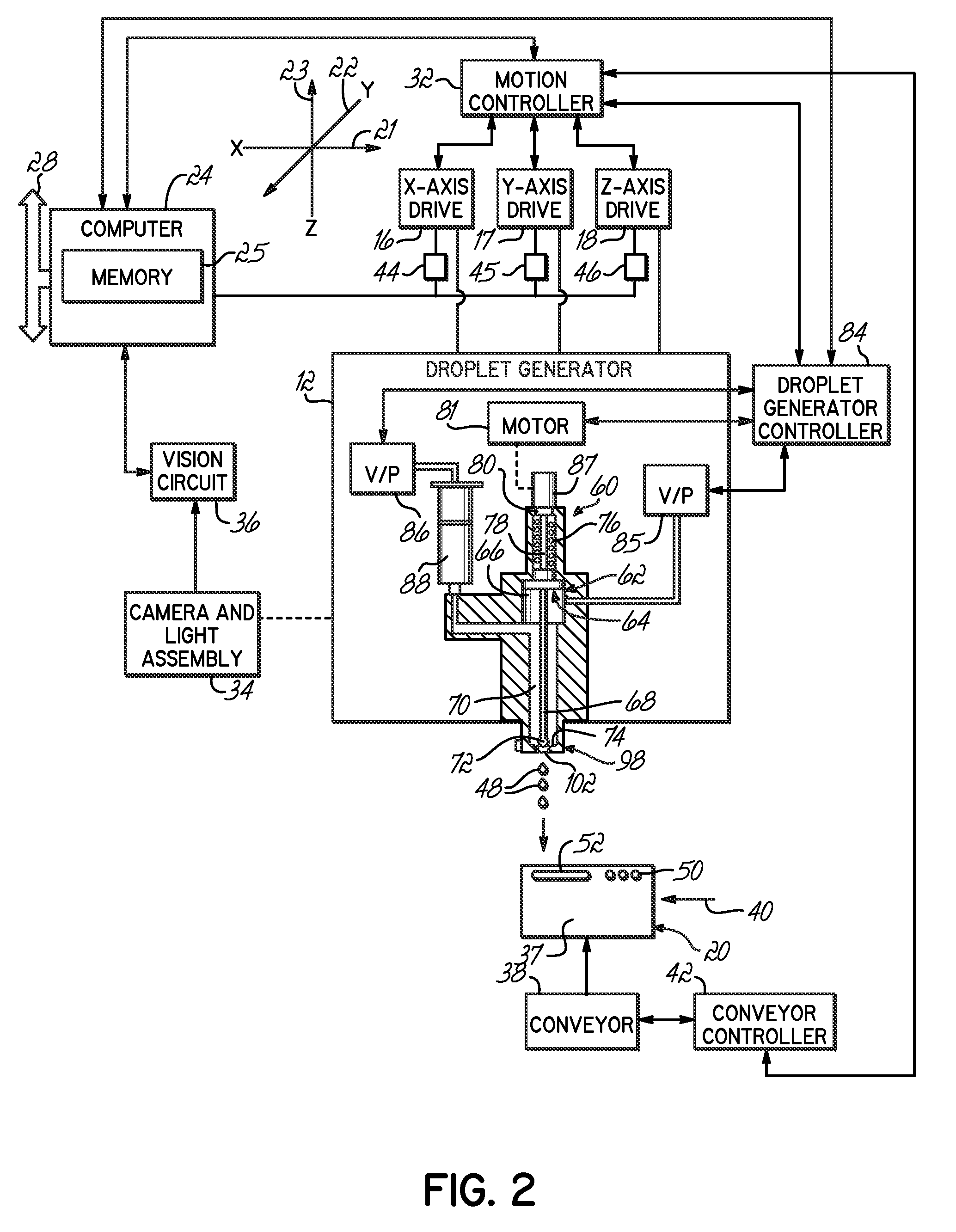
[0016]With reference to FIGS. 1 and 2, a fluid material jetting system 10 includes a cabinet 11 consisting of a framework of interconnected horizontal and vertical beams partially covered by panels. The jetting system 10 includes a fluid material droplet generator 12 for dispensing amounts 48 of a fluid material, for example, an adhesive, epoxy, solder, etc. The fluid material droplet generator 12 is mounted on a Z-axis drive mechanism 15 and suspended from an X-Y positioner 14 supported by the cabinet 11. The X-Y positioner 14 is operated by a pair of independently controllable axis drives 16, 17. Similarly, the z-axis drive mechanism 15 is operated by an axis drive 18. The X-Y positioner 14 and Z-axis drive mechanism 15 provide three substantially perpendicular motion axes for the droplet generator 12.

[0017]Axis drives 16, 17, 18 are capable of rapidly moving the droplet generator 12 over the surface of a substrate 20, such as a printed circuit board, relative to the multiple moti...


PUM

PropertyMeasurementUnit
cycle timeaaaaaaaaaa
total travel distanceaaaaaaaaaa
accelerationaaaaaaaaaa

Abstract

Methods for applying fluid materials to a substrate, such as circuit board, while continuously moving the fluid dispenser. Some methods generally involve correcting the dispense location for each of the dispensed amounts of fluid material by executing a statistical comparison of either the predicted and actual landing locations on the substrate, or the predicted and actual positions of the dispenser at each of the dispense locations. Other methods generally involve initiating the dispensing of amounts of the fluid material at dispense locations corrected by a correction factor specified in terms of the servo cycle for the movement of the dispenser or by a correction factor specified in terms of partial servo cycles courtesy of a timer.

Description

FIELD OF THE INVENTION[0001]The invention relates generally to methods for dispensing fluid materials and, more particularly, to methods for dispensing a fluid material, such as an underfill material, from a fluid dispenser onto a circuit board or other type of substrate.BACKGROUND OF THE INVENTION[0002]Mechanically-actuated “jetting” dispensers are commonly used in the electronics industry, to selectively dispense minute amounts or droplets of a highly viscous fluid material in a non-contact manner onto a circuit board. A typical jetting system includes an applicator or jetting dispenser with a pneumatically-operated needle having a valve element at one end that is configured to selectively engage a valve seat surrounding a discharge passage. Contact between the valve element and valve seat seals off the discharge passage from a chamber supplied with pressurized fluid material. To dispense droplets of the fluid material, the valve element is retracted from contact with the valve se...

Claims


Application Information

Patent Timeline
Patent Type & Authority Patents(United States)
IPC IPC(8): H05K1/02H05K13/04C23C16/52H05K3/00
CPCH05K2203/163H05K2203/0126H05K13/0465H05K3/0005H05K3/0008H05K1/0269H05K3/1241H05K2203/013B05B12/084H05K3/125
Inventor ABERNATHY, RONALD N.MAIORCA, PHILLIP P.QUINONES, HORATIORATLEDGE, THOMASFOWLER, CLIFFORD A.
Owner NORDSON CORP
Learn More