Coring tool alignment assembly

a technology of alignment assembly and coring tool, which is applied in the direction of branching pipes, manufacturing tools, transportation and packaging, etc., can solve the problems of complex devices that usually require many parts, and the connection is usually structurally unstable, so as to improve the resistance of the pipe to crushing failure

Active Publication Date: 2014-07-08
ADVANCED DRAINAGE SYST
View PDF65 Cites 5 Cited by
  • Summary
  • Abstract
  • Description
  • Claims
  • Application Information

AI Technical Summary

Benefits of technology

[0009]The complexity of engaging a mainline pipe to secure a guide thereto for controlled movement of a connected coring device is increased when the mainline pipe includes outwardly protruding features such as spaced-apart ribs. Such ribs are sometimes attached or integrally formed with the pipe to enhance the pipe's resistance to crushing failure.

Problems solved by technology

If the tool and resulting hole are not properly aligned, the central axis of the hole will not intersect the long axis of the mainline pipe.
This can result in attendant misalignment of the service connection with the mainline pipe, hence misalignment of the service lateral, which can lead to leaking and eventual structural failure of the connection.
In such an instance, and especially where the cored hole is not quite circular, the excessive force may cause an undesirable amount of penetration of the sleeved end of the hub into the mainline pipe, which can result in interference with the operation and / or inspection of the mainline pipe.
There exists in the prior art complicated tools for engaging a mainline pipe to secure a platform or guide apparatus on a pipe for controlled movement of a connected coring device to form the hole in the pipe sidewall.
Such complicated devices usually require many parts and are cumbersome, especially in an environment where a lateral connection is made to, for example, an existing main sewer line that has been exposed, in place, several feet underground.
Moreover, in some construction environments, rainwater, mud, debris, and other elements may make it extremely difficult and / or time consuming for a worker to use conventional mechanisms for controlling coring tools to produce a properly formed hole.
The complexity of engaging a mainline pipe to secure a guide thereto for controlled movement of a connected coring device is increased when the mainline pipe includes outwardly protruding features such as spaced-apart ribs.

Method used


Image

  • Coring tool alignment assembly
  • Coring tool alignment assembly
  • Coring tool alignment assembly

Examples


Embodiment Construction

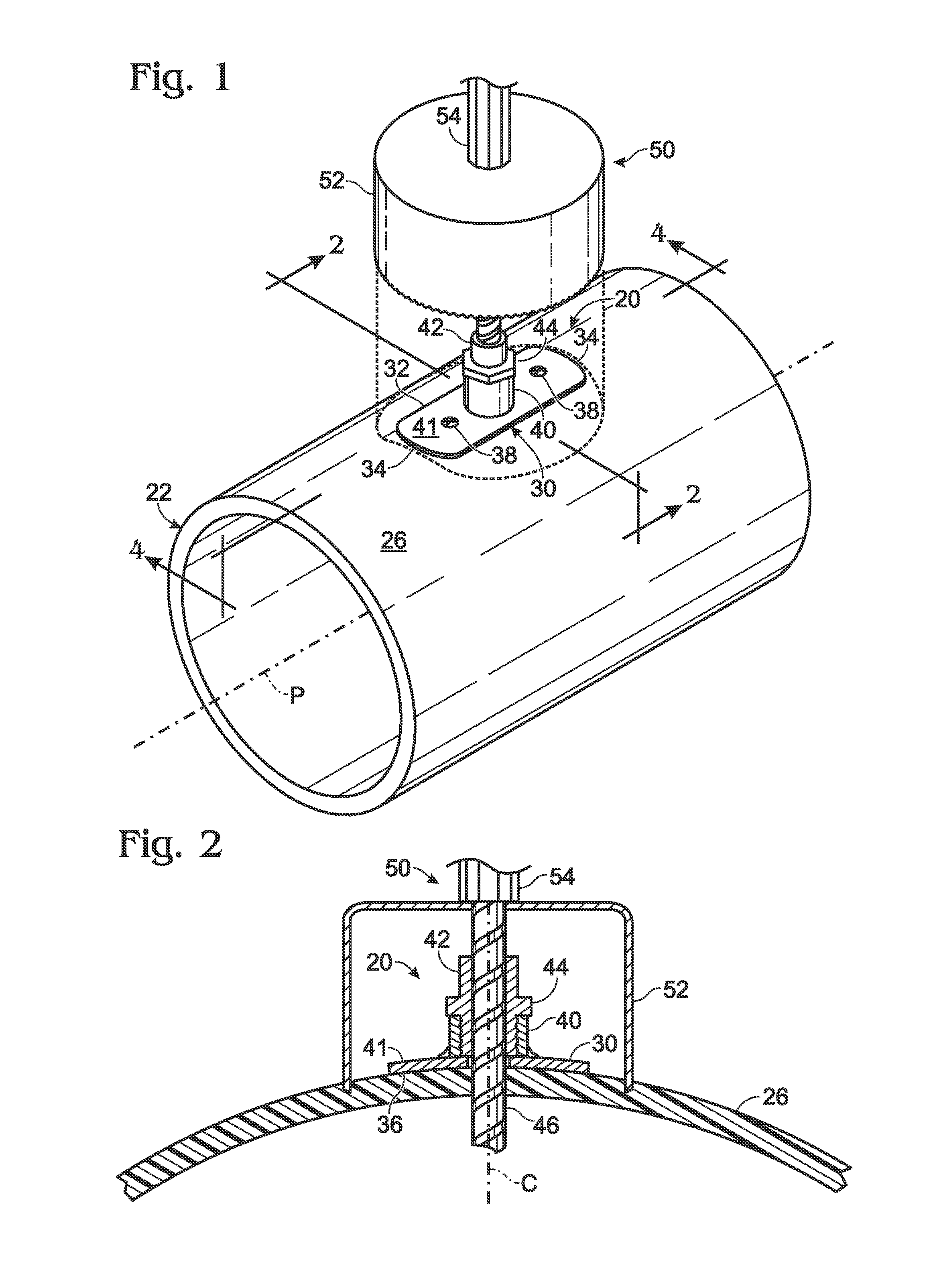
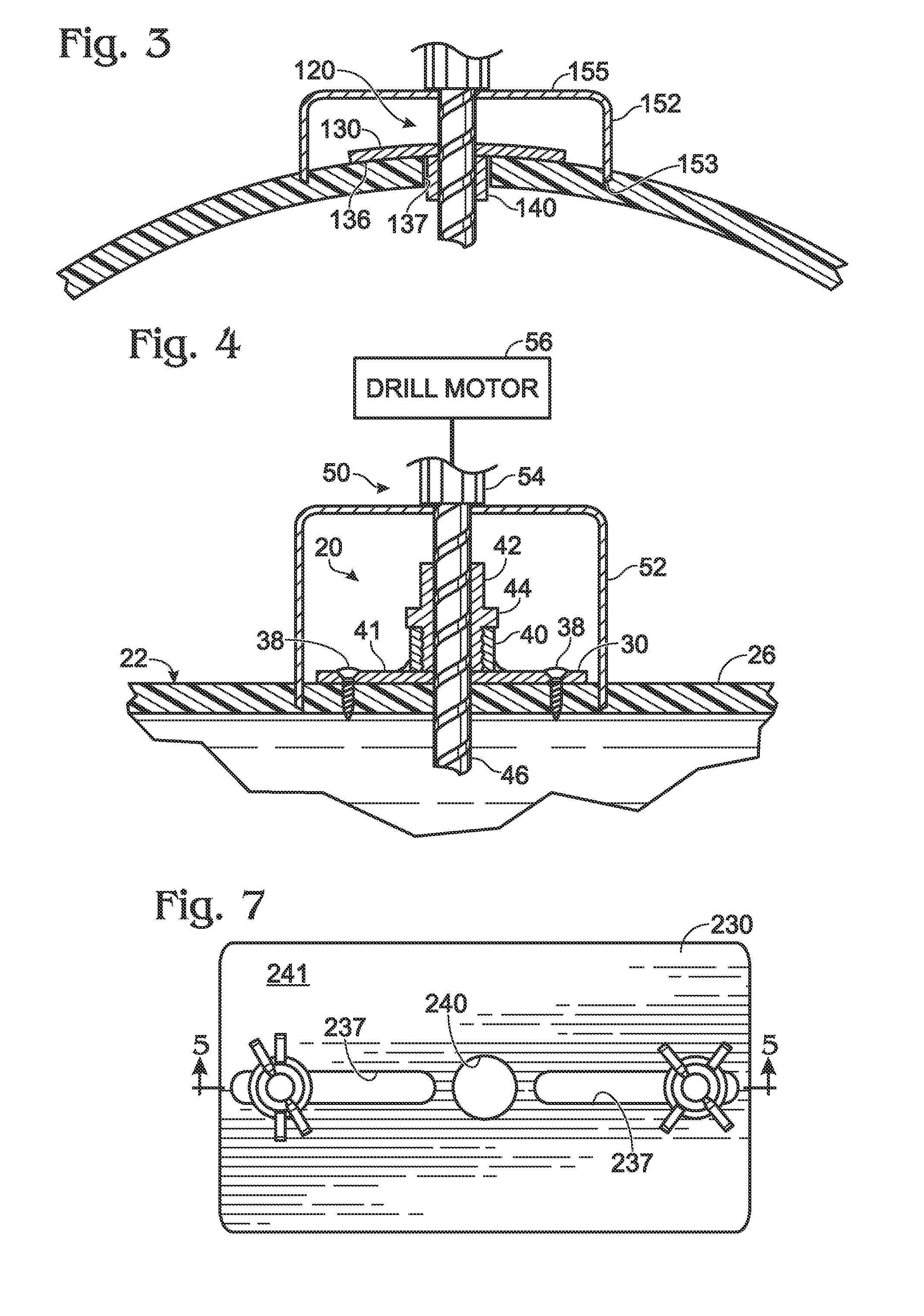
[0031]One embodiment of an assembly 20 for aligning a coring tool relative to a pipe sidewall 26 is shown in FIG. 1 connected to the mainline pipe 22 as the hole saw 52 of a coring tool 50 is rotated and advanced toward the pipe 22 for cutting a hole in the sidewall 26 of the pipe.

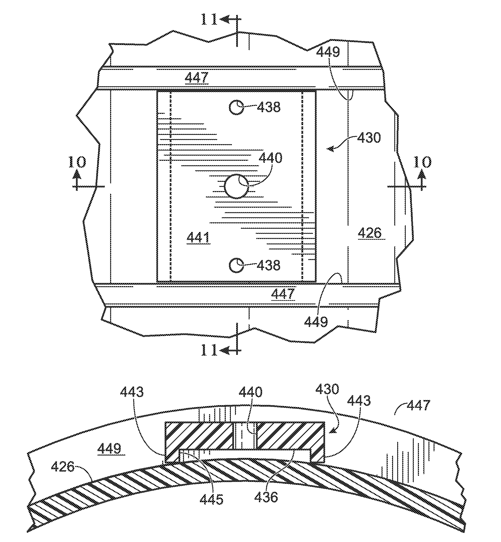
[0032]With particular reference to FIGS. 1, 2, and 4, the alignment assembly includes a rigid base plate 30 having straight, parallel side edges 32 and rounded end edges 34. As best seen in FIG. 2, the base plate 30 is preferably shaped to conform to the curvature of the exterior of the pipe sidewall 26. Thus, for smooth-sided pipes, such as a PVC sewer pipe as depicted here, the underside 36 of the base plate 30 abuts the exterior of the pipe sidewall 26.

[0033]Although a smooth-walled pipe 22 is shown in the figures, it is contemplated that the present assembly is may be employed with corrugated, ribbed and other pipe sidewall shapes and surfaces as described more below.

[0034]In one embodiment, the base p...


PUM

PropertyMeasurementUnit
bore diameteraaaaaaaaaa
thicknessaaaaaaaaaa
radiiaaaaaaaaaa

Abstract

A compact assembly for aligning a coring tool relative to a pipe sidewall. The coring tool includes a hollow, cylindrical hole saw mounted to an arbor that has an elongated pilot shaft centered in the hole saw. The assembly is made up of a base plate that is attachable to the pipe sidewall. In one embodiment, a tubular sleeve is mounted to the base plate and has a bore diameter sized for receiving the pilot shaft as the hole saw is advanced toward and saws through the pipe wall, and the entire assembly is sized to fit inside the hole saw as the hole saw saws through the pipe sidewall. In another embodiment, the base plate is configured for use with pipe sidewalls that include outwardly protruding ribs.

Description

FIELD OF THE INVENTION[0001]This invention generally pertains to what is known as a service connection between a mainline wastewater or storm water pipe and a lateral connecting pipe. More specifically, this invention relates to an assembly that facilitates precise formation of a hole through the sidewall of the mainline pipe for securely connecting the main and lateral pipes.BACKGROUND AND SUMMARY OF THE INVENTION[0002]Gravity-type pipe conveyance systems for waste or storm water generally include a mainline pipe or conduit to which service lateral pipes are connected. Many applications call for the connection of the lateral pipes to be made such that the lateral is perpendicular to the mainline pipe. Such service connections are often referred to as “Tee” connections. Alternatively, the service lateral pipe can be connected at an angle (although with the long axis of the lateral preferably always intersecting the long axis of the mainline pipe) and is thus designated, for example,...

Claims


Application Information

Patent Timeline
Patent Type & Authority Patents(United States)
IPC IPC(8): B23B49/02B23B47/28
CPCB23B47/281B23B51/0426B23B2270/58F16L41/04F16L41/08Y10T408/56238Y10T408/03Y10T408/558Y10T408/567Y10T408/895Y10T408/569Y10T408/98
Inventor MARTIN, FRANK, P.
Owner ADVANCED DRAINAGE SYST
Why Eureka
Try Eureka