Chemical looping combustion method and plant with independent solid circulation control

a combustion method and loop technology, applied in the field of chemical loop combustion, can solve the problems of less control of solid circulation, and inability to control the inner circulation of solids in the loop

Active Publication Date: 2014-07-08
TOTALENERGIES ONETECH +2
View PDF8 Cites 21 Cited by
  • Summary
  • Abstract
  • Description
  • Claims
  • Application Information

AI Technical Summary

Problems solved by technology

However, in conventional industrial fluidized bed combustion processes, the technologies used do not allow the inner circulation of solids in the loop to be controlled independently.
The return leg is dimensioned so as to promote solid recycling but it does not allow solid circulation control.
However, in such systems, the circulation of solids within the loop entirely depends on the amount of combustion air fed into the circulating bed.
Unfortunately, operation of these valves on group B particles is more delicate.
In fact, it is impossible to maintain group B particles fluidized without forming large gas bubbles that disturb the flow.
Furthermore, the moving parts of these valves exposed to the flow cannot be exposed to very high temperatures (>900° C.).
The various methods provided so far do not allow independent control of the oxide circulation.
Such a system does not allow to control the circulation of metal oxides independently of the air flow rate in the oxidation reactor.
These siphons do not allow to control and to modify the circulation of metal oxides.
It is therefore not possible to control the circulation of metal oxides using mechanical valves conventionally used in other processes such as FCC.

Method used


Image

  • Chemical looping combustion method and plant with independent solid circulation control
  • Chemical looping combustion method and plant with independent solid circulation control
  • Chemical looping combustion method and plant with independent solid circulation control

Examples


example

[0118]The example of a circulation loop dimensioned according to the main characteristics of the invention and used under ambient reactionless conditions is given hereafter in order to illustrate the operation of the invention.

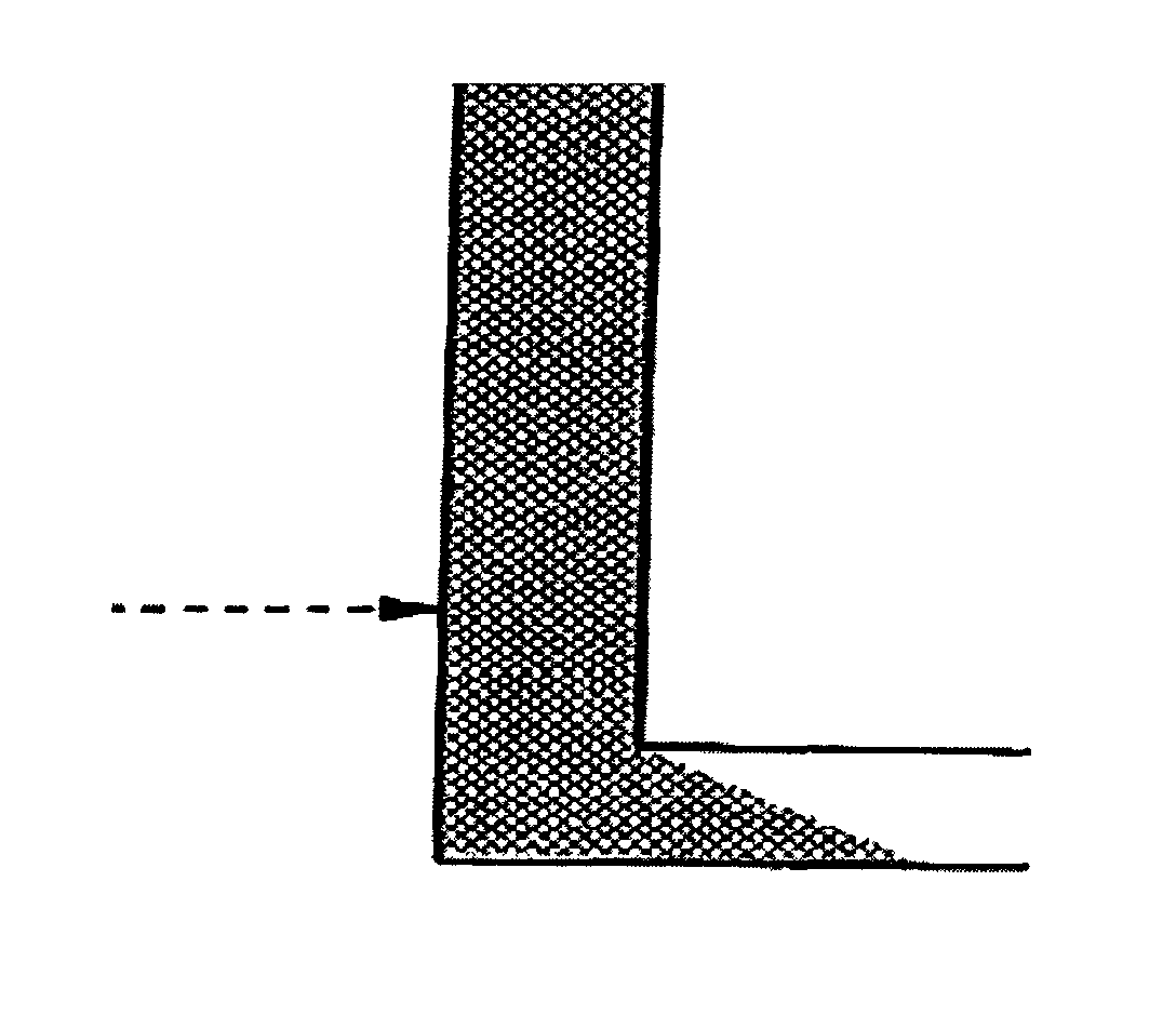
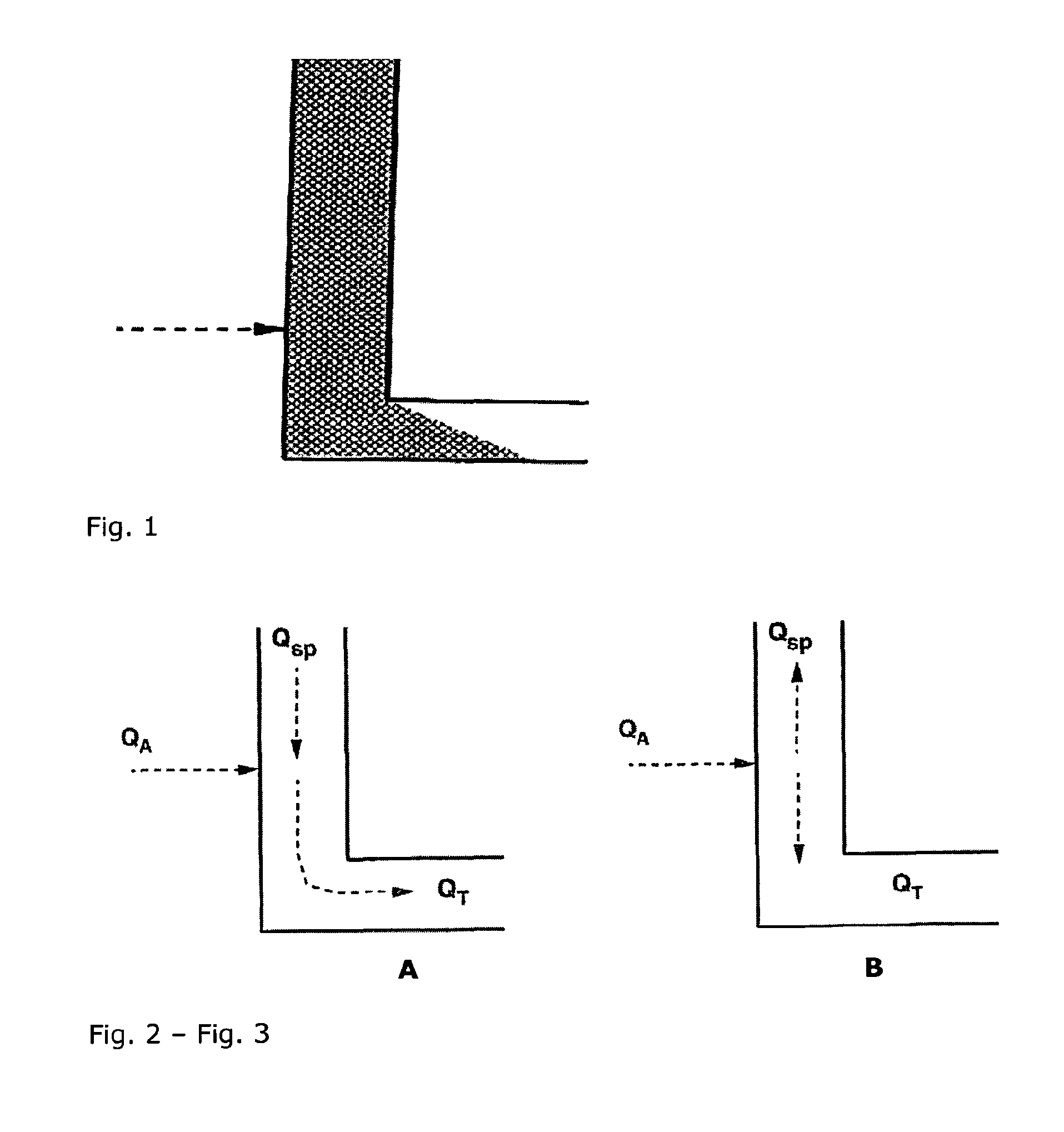
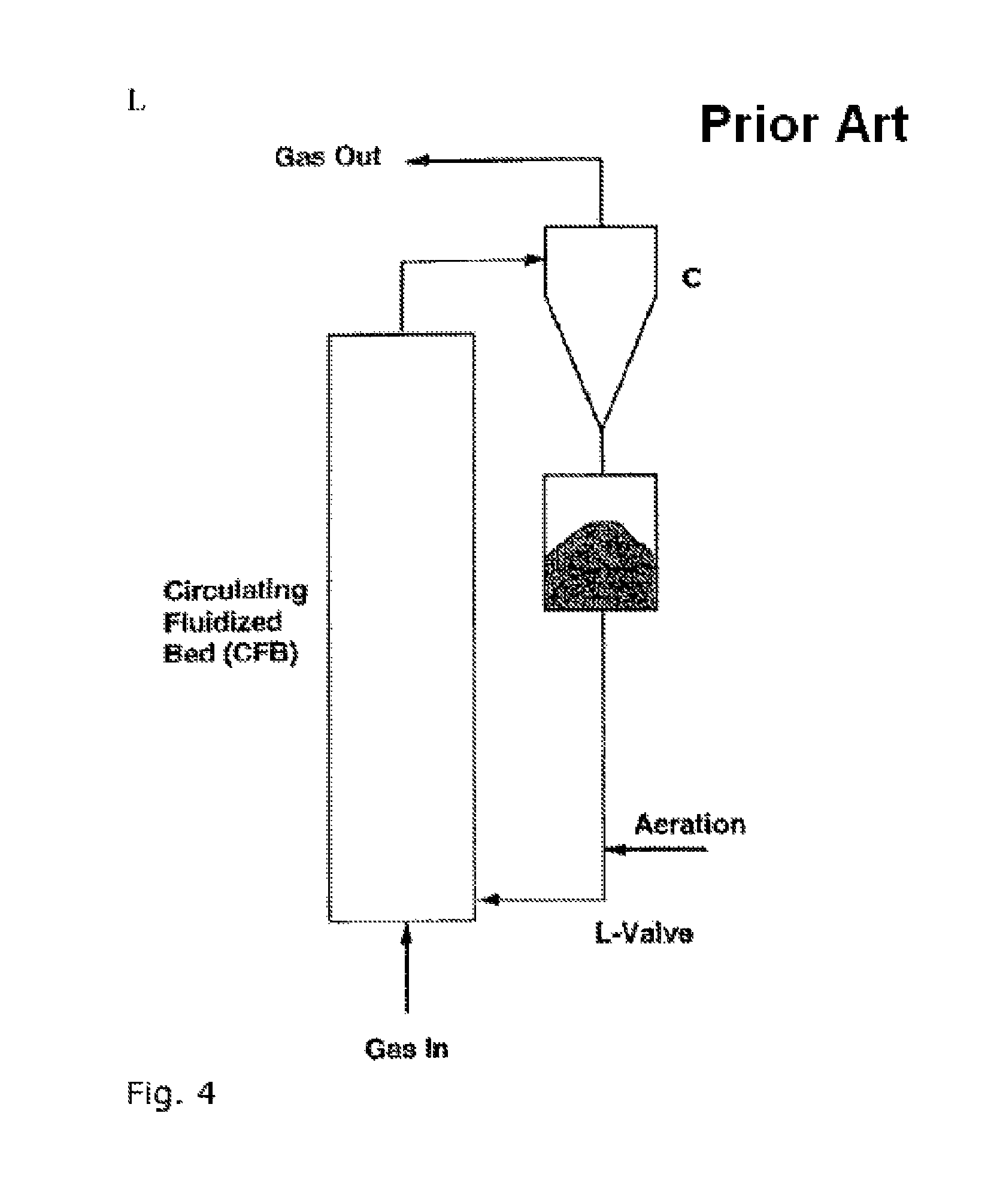
[0119]The model (FIG. 11) mainly consists of two identical fluidized beds R1 and R2, 10 cm in diameter, connected to one another by two loops referred to as circulating loops. Each loop is made up of a 20-mm diameter and 2.5-m long lift (ascending transport line) supplied by an L-valve, also referred to as L-shaped leg, consisting of a vertical section and of a horizontal section of equal diameter (16 mm) wherein an aeration gas is injected at an elevation of 30 mm in relation to the bottom of the L-valve. The particles are withdrawn from the fluidized bed (R1 or R2) at the top of the vertical part (Vv1 or Vv2) of the L-valve. They flow through the vertical part, then the horizontal part (Vh1 or Vh2) of the L-valve. They are then carried to a lift (L1 or L2) a...


PUM

PropertyMeasurementUnit
temperaturesaaaaaaaaaa
temperatureaaaaaaaaaa

Abstract

The invention relates to an improved plant and method for chemical looping combustion of at least one hydrocarbon feed with independent control of the circulation of the solid active mass particles between the fluidized bed reaction zones, by means of one or more non-mechanical valves of L-valve type.

Description

FIELD OF THE INVENTION[0001]The invention relates to the sphere of chemical looping combustion. In the text hereafter, what is referred to as a chemical looping combustion (CLC) process is a loop oxidation-reduction or redox process on active mass. It can be noted that, in general, the terms oxidation and reduction are used with regard to the oxidized or reduced state of the active mass respectively. The oxidation reactor is the reactor wherein the redox mass (<<active mass>> or <<oxygen carrier>>) is oxidized and the reduction reactor is the reactor wherein the redox mass is reduced. During reduction of the redox mass, the fuel can be either totally oxidized, producing CO2 and H2O, or partly oxidized, producing syngas CO and H2.[0002]Oxidation of the active masses can be performed in air or in the presence of a gas that can yield oxygen under the process conditions, such as water vapour for example. In this case, oxidation of the active masses allows to prod...

Claims


Application Information

Patent Timeline
Patent Type & Authority Patents(United States)
IPC IPC(8): C01B3/24C01B3/38
CPCF23C2900/99008C10J3/721Y02E20/346C10J3/725F23C99/00C10J3/723C10J2300/1606Y02E20/34
Inventor GAUTHIER, THIERRYHOTEIT, ALIFORRET, ANN
Owner TOTALENERGIES ONETECH
Why Eureka
Try Eureka