Continuous-flow deformability-based cell separation

a deformation-based cell and flow technology, applied in biomass after-treatment, instruments, enzymology, etc., can solve the problems of organ failure, coma, and ultimately death, and achieve the effect of reducing or eliminating the clogging of said sorter

Inactive Publication Date: 2014-07-08
MASSACHUSETTS INST OF TECH
View PDF2 Cites 2 Cited by
  • Summary
  • Abstract
  • Description
  • Claims
  • Application Information

AI Technical Summary

Benefits of technology

[0012]In one embodiment, the cell separation rate is less than 0.1 seconds per cell. In one embodiment, the cell separation rate ranges between 0.1-1 seconds per cell. In one embodiment, the method reduces or eliminates clogging of said sorter. In one embodiment, the force field at a non-zero angle with respect to the length of said trenches is an electrostatic force field. In one embodiment, the electrostatic force field provides an electroosmotic driving force for said fluid. In one embodiment, the force field is a pressure-driven fluid flow. In one embodiment, the fluid has an ionic strength of about 1-1000 mM.

Problems solved by technology

Often, increases in blood cell stiffness lead to loss of the cells' ability to squeeze through capillaries, resulting in organ failure, coma, and ultimately death.

Method used


Image

  • Continuous-flow deformability-based cell separation
  • Continuous-flow deformability-based cell separation
  • Continuous-flow deformability-based cell separation

Examples


example 1

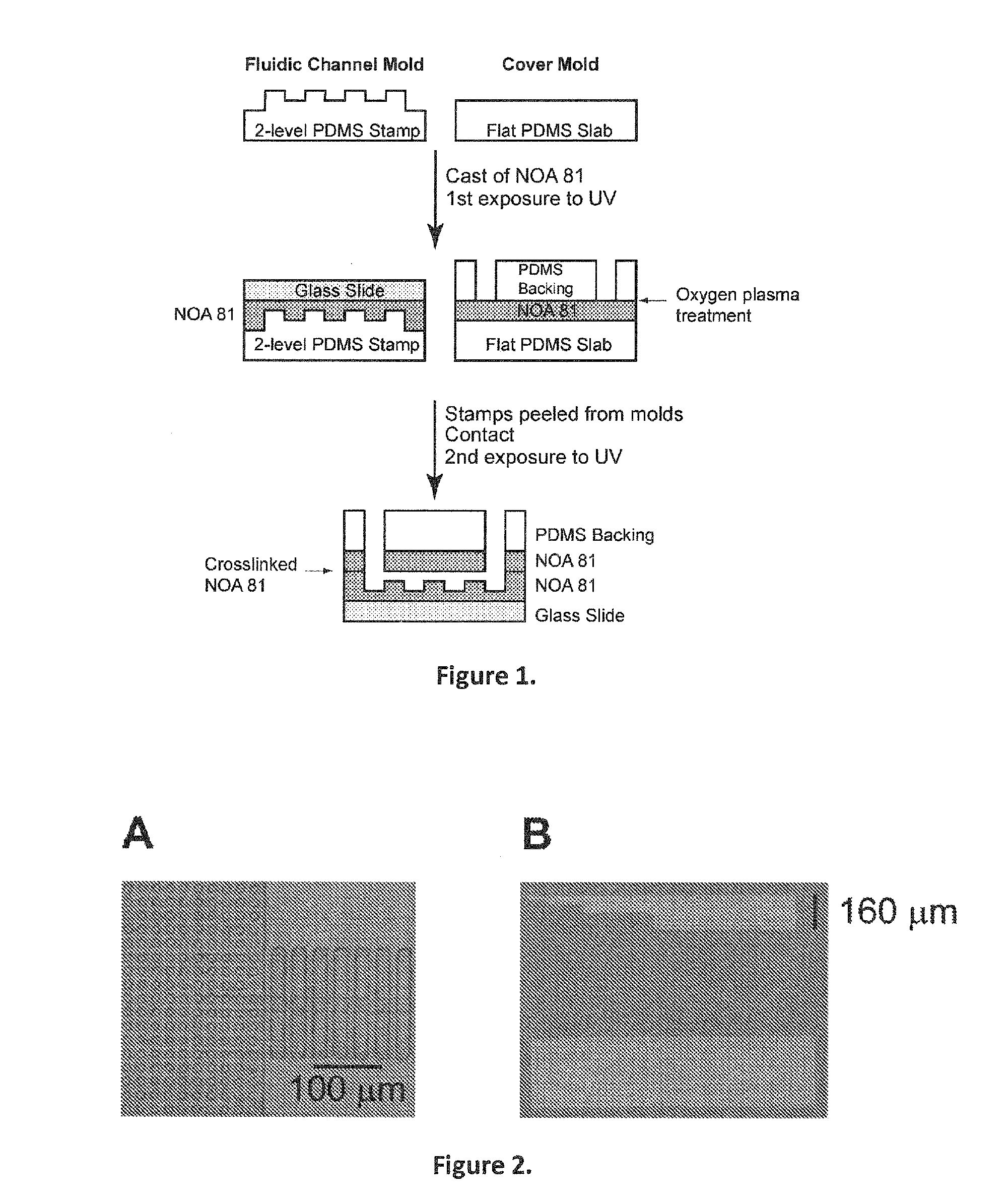
Fabrication of a Microseparator

[0185]In one embodiment, to construct a device, the following procedure was used:[0186]1. Holes were punched in a PDMS backing with a biopsy punch, leaving the bores in place.[0187]2. Scotch tape was used to remove dust and contaminants from the PDMS backing.[0188]3. Glass slide was cleaned with tissue paper (such as “kimwipe”).[0189]4. Glass slide and the PDMS backing were placed in oxygen plasma (2 minutes vacuum pump, 1 minute oxygen plasma exposure).[0190]5. A drop of NOA was placed on the flat PDMS Slab and another drop on the 2-level PDMS Stamp.[0191]6. The PDMS Backing was pushed on the Flat PDMS Slab, being careful to eliminate any trapped bubbles.[0192]7. The Glass Slide was pushed on the 2-level PDMS stamp being careful to eliminate any trapped bubbles.[0193]8. Both sandwiched components were exposed to a UV DNA gel viewer for 1 minute and 20 seconds.[0194]9. Bores and NOA 81 were removed from the PDMS Backing.[0195]10. The pieces from the 2-...

example 2

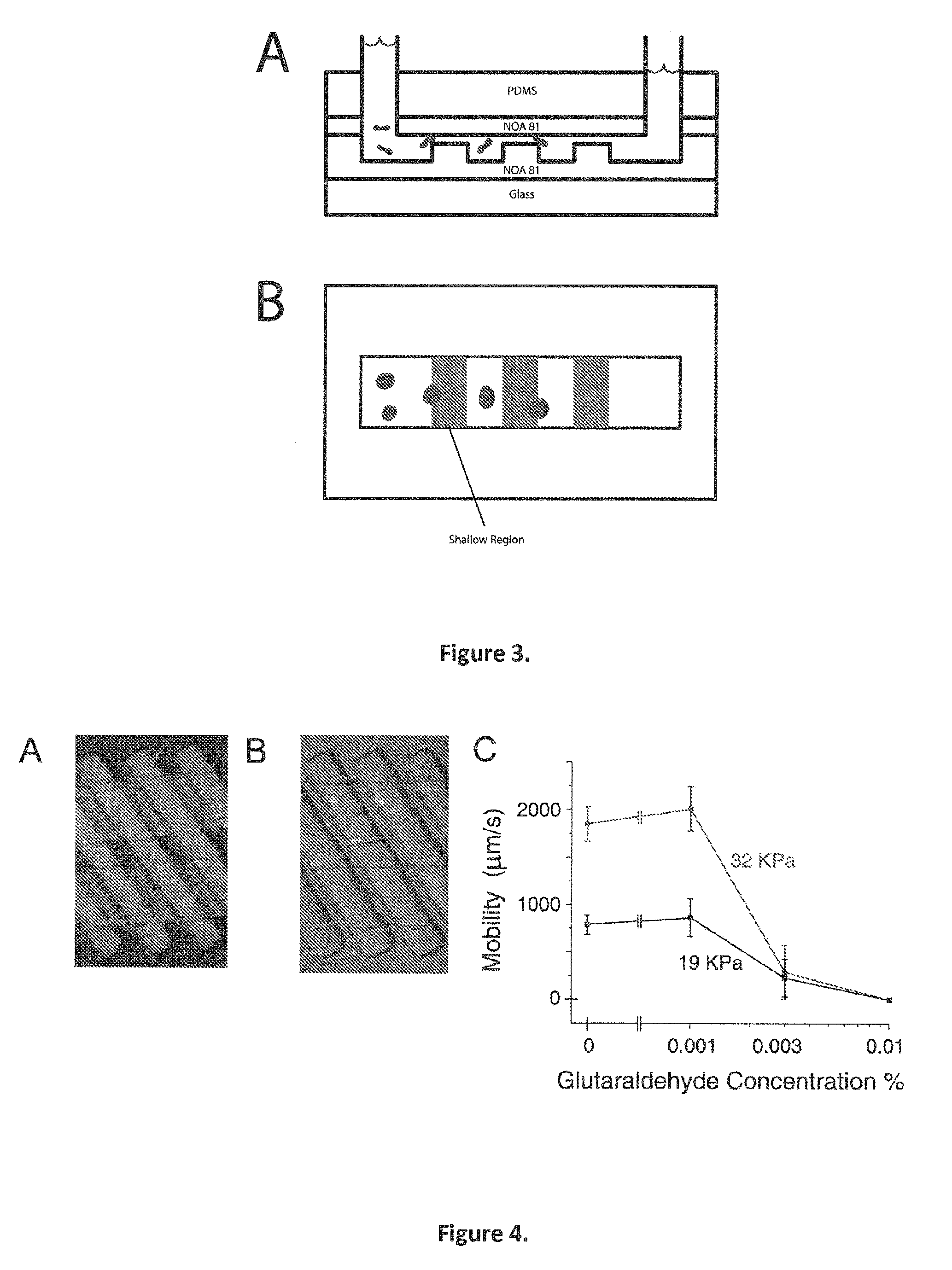
Operation of the Sorter

[0199]With reference to FIG. 4A, a solution of PBS 1× and 0.2% w / v Pluronic F108 (a surfactant) and Bovine Serum Albumin 1% w / v (another surfactant) was prepared. The device was filled with this solution by applying pressure to one of the reservoirs. 1 μL of whole blood was mixed with 100 μL of this solution. The mixture was injected into the entrance reservoir of the device shown by using a syringe. The pressure difference between the two reservoirs was 40 kPa and was generated by using a pressure regulator. The cell concentration was approximately 0.5% hematocrit. Mobility was measured by tracking individual cells over a distance of 100 μm.

example 3

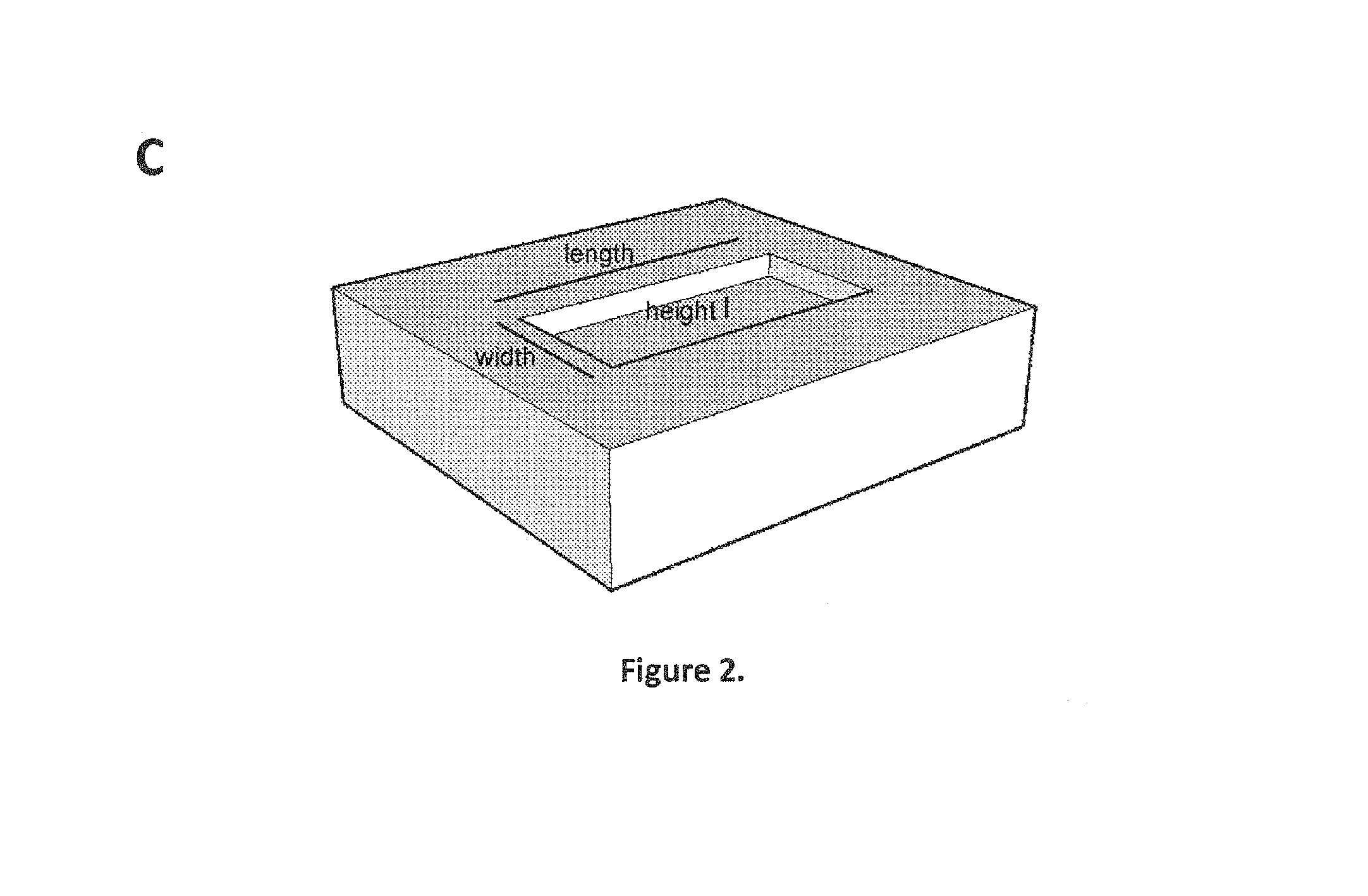
Operation of the Microseparator

[0200]With reference to FIG. 6, the solution used in this device is the same as that used in example 2. To create the Glutaraldehyde-treated cells, 1 μL of whole blood was mixed in 0.003% Glutaraldehyde in PBS 1× and allowed to sit for 30 minutes. The cells were then washed 3 times with the PBS-Pluronic-BSA solution. The pressure difference across the reservoirs was 1 atmospheres vertically and 1 atmospheres horizontally. 100 cells were measured for each population at a displacement of 550 μm from the injection point. The shallow region of the device was 2.1 μm and the deep region of the device was 8.8 μm. 20 sorting units were in the device array, with a period between units of 20 μm. The operation temperature was room temperature, 23° C. Locations were measured as cells passed 550 μm from the point of injection.


PUM


Abstract

This invention provides methods utilizing a microfluidic device that can quickly and accurately discern differences in deformability between individual cells and sets of cells and continuously fractionate populations of cells based on their deformability. This information may be important in disease diagnosis and treatment efficacy monitoring. For example such a device may be able to determine the stage of malarial infection by using red blood cell deformability. Additionally, methods of the invention may be used as a tool to screen drugs that can make cells more flexible in diseases such as sickle cell anemia that causes sickle cell crises. The relatively low manufacturing and operation costs of methods of the invention enable this device to be used in resource-limited settings to diagnose and monitor disease.

Description

CROSS REFERENCE TO RELATED APPLICATIONS[0001]This application claims the benefit of U.S. Ser. No. 61 / 249,167, filed on 6 Oct. 2009 which is incorporated in its entirety herein by reference.BACKGROUND OF THE INVENTION[0002]Change in cell stiffness is a characteristic of several hematological diseases. Examples of such diseases may involve red blood cells (e.g. malaria and sickle cell anemia), white blood cells (leukemia and leukostasis), and metastatic solid-organ tumor cells (circulating tumor cells and the more extreme carcinocythemia). Often, increases in blood cell stiffness lead to loss of the cells' ability to squeeze through capillaries, resulting in organ failure, coma, and ultimately death.SUMMARY OF THE INVENTION[0003]In one embodiment, this invention provides a method of sorting a fluid mixture comprising a plurality of cells, said method comprising the steps of:[0004]i. loading a fluid mixture comprising a plurality of cells in a cell sorter comprising:[0005]a first subst...

Claims


Application Information

Patent Timeline
Patent Type & Authority Patents(United States)
IPC IPC(8): A01N1/02
CPCC12N13/00C12M47/04C12Q1/025G01N33/5008G01N33/5091
Inventor HAN, JONGYOONBOW, HANSENABGRALL, PATRICK
Owner MASSACHUSETTS INST OF TECH
Why Eureka
Try Eureka