
Color display converter for pinball machines

a technology of pinball machines and converters, applied in the field of color display converters for pinball machines, can solve the problems of high cost of redesigning software and hardware systems, preventing the introduction of color displays and upgrades

Active Publication Date: 2014-07-08
PERLOW RANDALL BRET
View PDF15 Cites 7 Cited by
  • Summary
  • Abstract
  • Description
  • Claims
  • Application Information

AI Technical Summary

Benefits of technology

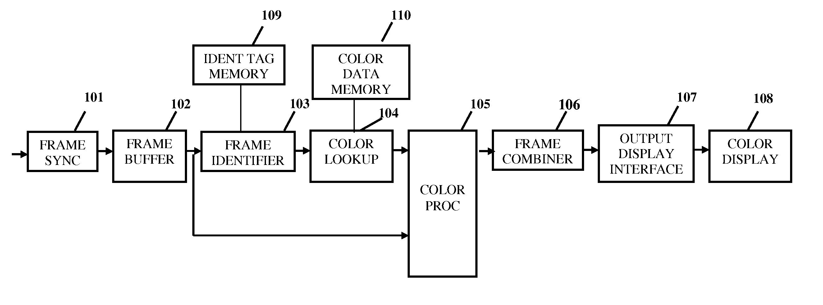
[0005]The display device disclosed herein addresses the needs discussed above, discussed below and those that are known in the art. The display device disclosed herein is for use in conjunction with older pinball machines. The display device enhances the players experience by converting the game's standard grayscale video display to an upgraded video display. By way of example and not limitation, the upgraded video display may include a full-color representation, or a full-color high resolution representation. The display device may be connected to the pinball machine and provide improved visual experience without modification of game (e.g., pinball) software and is compatible with the game's existing display port. When properly connected to a pinball machine, the device may identify the received grayscale video frames in real-time, and retrieve associated color data stored within the device. The retrieved color data is used to either enhance or replace the original grayscale video frame to an improved color video frame. The improved color video frame may be output to a high resolution color display.
[0007]The display device may utilize a game's normal interface and cable to connect to the game's display port, making it easy to replace a standard low-resolution, monochrome (also referred to as grayscale), dot-matrix display with a multicolor displayor a high resolution full color display.
[0008]The display device may also produce an enhanced colorized video frame by combining a received monochrome video frame with color data stored internal to the device.

Problems solved by technology

Over the last two decades, many players and pinball collectors have sought an upgrade to this aging display technology but the high cost of redesigning software and hardware systems has impeded the introduction of color displays and upgrades.

Method used


Image

  • Color display converter for pinball machines
  • Color display converter for pinball machines
  • Color display converter for pinball machines

Examples


Embodiment Construction

[0017]Referring now to the drawings, the display device may include software and hardware. The hardware components may include a connector which connects the display device to the video output port of an existing game. The connector receives data from the video output port of the existing game. The hardware components may also include one or more microprocessors, microcontrollers, or programmable logic devices (including field-programmable gate arrays, or FPGAs) which use software to process game data and generate a new color video output signal. The software includes a frame synchronizer 101 which organizes the data into frames. The software also includes a frame identifier 103 which identifies the frames organized by the frame synchronizer 101 by generating a unique tag for each frame. The generated tag may be compared to preprogrammed tags of frames in a tag lookup table 109. The preprogrammed tags may be associated with multicolor or high resolution graphical data which can be c...


PUM


Abstract

A later generation display device may be connected to the video output port of an older electronic device which utilized an earlier generation display such as a dot matrix display. The early generation display is replaced with the later generation display. The display device includes software which receives graphic data through the video output port and identifies which frame is currently being streamed. The display device matches the frame being streamed to a stored graphic frame having a higher resolution and / or color. The matched frame is delivered to the later generation device so that the user can experience a higher quality visual effect by retrofitting the older electronic device with the later generation display.

Description

CROSS-REFERENCE TO RELATED APPLICATIONS[0001]This application claims the benefits of provisional patent application Ser. No. 61 / 434,434, filed on Jan. 20, 2011, the entire contents of which is expressly incorporated herein by reference.STATEMENT RE: FEDERALLY SPONSORED RESEARCH / DEVELOPMENT[0002]Not ApplicableBACKGROUND[0003]The display device disclosed herein relates to a method and device for upgrading or altering a visual effect of an older machine having an earlier generation monitor (e.g., monochrome monitor).[0004]Since the early 1990s, pinball games have incorporated low resolution (most commonly, 128×32), monochrome, dot-matrix displays to provide video animation and score information during gameplay. Games using these displays are generally capable of producing only grayscale (intensity only) video. The video usually contains 4-16 intensity levels, generated by transmitting a sequence of video frames to the dot-matrix display at a predetermined frame rate (e.g., greater than...

Claims


Application Information

Patent Timeline
Patent Type & Authority Patents(United States)
IPC IPC(8): G09G5/02G06F3/038G09G5/00
CPCG09G5/04G09G5/003G06T11/001A63F7/027G09G3/2003G09G5/026G09G5/10G09G5/12G09G5/391G09G2340/08G09G2360/18G09G2370/00H04N5/44
Inventor PERLOW, RANDALL, BRET
Owner PERLOW RANDALL BRET
Learn More