System and method for obtaining and using downhole data during well control operations

a technology well control operations, applied in the field of system and method for obtaining and using downhole data during well control operations, can solve the problems of loss of well control, damage to operation, and mud to be los

Inactive Publication Date: 2014-07-15
WEATHERFORD TECH HLDG LLC
View PDF15 Cites 7 Cited by
  • Summary
  • Abstract
  • Description
  • Claims
  • Application Information

AI Technical Summary

Problems solved by technology

For example, a mud weight that exceeds the fracture strength of the exposed portion of the formation 16 below the casing 12 in the wellbore 10 can fracture the formation 16 and cause mud to be lost, and potentially result in loss of well control.
This causes a “kick” or influx of formation fluid (liquid, gas, or both) into the wellbore 10 that can be detrimental to the operation.
While important in all drilling applications, these tests and measurements area of even greater importance when drilling with a subsea BOP 20 where the choke and kill lines 50 / 60 may be up to 10,000-feet in length and may produce more significant pressure losses in the choke and the kill lines, which greatly complicates maintaining wellbore pressure within the desired limits during the well control operations.
However, this is not the case for a subsea BOP, where the choke line 60 is generally at least several hundred feet long.
Any damage to the formation 16 can cause partial or complete loss of returns and can create situations that will take considerable time and additional strings of casing 12 to regain well control and return to normal drilling operations.
Because the bottom hole pressure is determined from the sum of the casing pressure at the surface, the annular pressure, and the choke line friction pressure, the accuracy and the reliability of pressure measurements and calculations can be particularly difficult to obtain reliably on deepwater drilling rigs using subsea BOP stacks.
Use of inaccurate choke line friction pressures when circulating out a kick in such an implementation could result in either an increase or decrease in the bottom hole pressure that could damage the formation 16 or cause a secondary fluid influx.
Unfortunately, obtaining choke line friction pressures periodically throughout the drilling process only provides for the mud properties at one moment in time.
Consequently, the friction pressure losses will also generally change significantly when the original weight mud is weighted up to provide the kill weight mud.
In addition to the above problems, prior art well control operations can be time consuming and can require extensive planning, calculations, monitoring, and human intervention to execute.
Furthermore, current well control operations are not open to much flexibility.
In another example, both the Engineer's and Driller's methods for well control use substantially constant pump rates to maintain control while executing the operation, which is not always ideal or achievable.
Not only do the prior art methods consume additional rig time and thereby increase costs to the operator and risks to the well control operations, but they also provide a less than optimal ability to determine accurate bottom hole pressure.
As will be appreciated, the combination of mud, formation cuttings, and influx fluid(s) in the wellbore can vary significantly foot-by-foot and over time and can create uncertainty in the determination of the actual wellbore pressure in the annulus.
Moreover, obtaining accurate choke line pressure losses poses another problem in determining the actual wellbore pressure in the annulus.
This problem with accurate choke line pressure losses may be particularly acute on a subsea BOP and especially in deepwater, where the effects of temperature and pressure can cause choke line friction pressures to be significantly inaccurate.

Method used


Image

  • System and method for obtaining and using downhole data during well control operations
  • System and method for obtaining and using downhole data during well control operations
  • System and method for obtaining and using downhole data during well control operations

Examples


Embodiment Construction

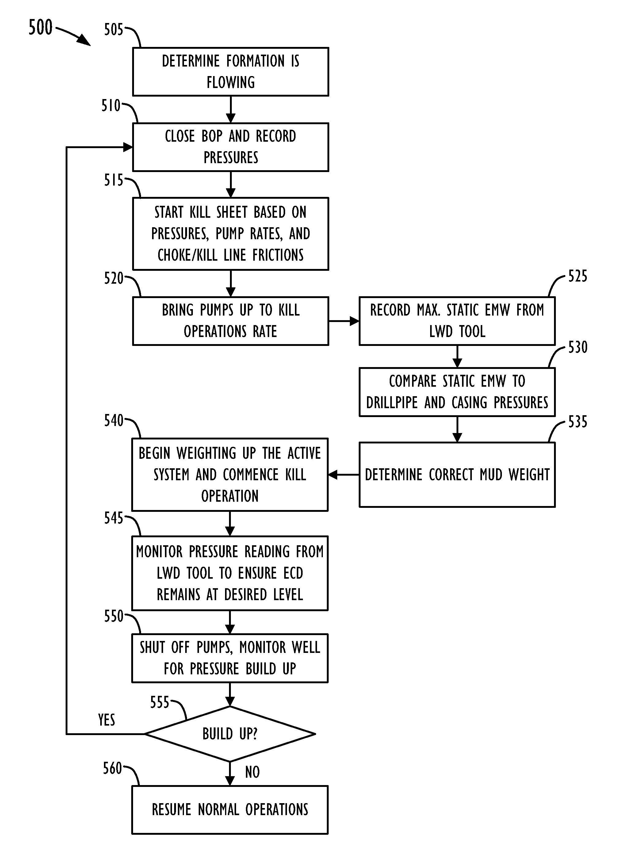
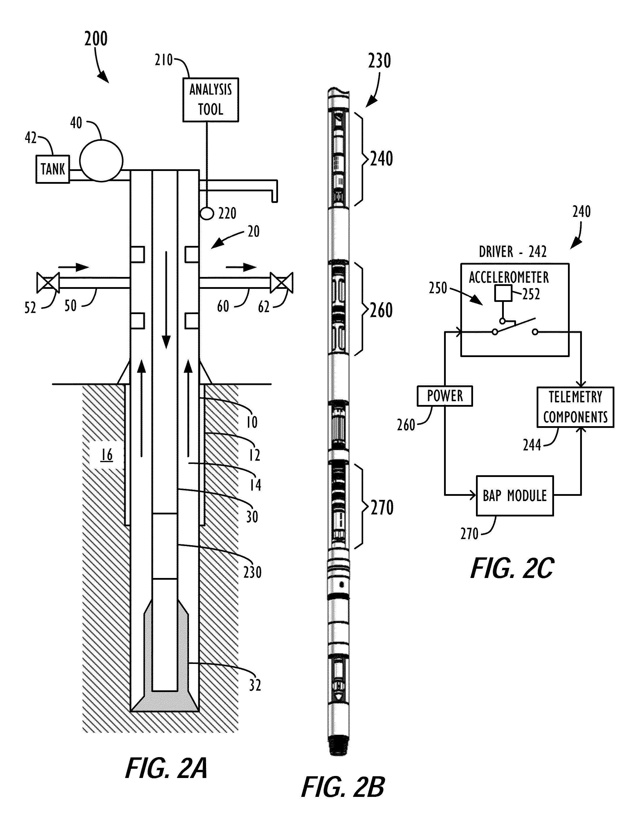
[0031]FIG. 2A illustrates a drilling system having a well control system 200 according to one embodiment of the present disclosure. The well control system 200 includes analysis tools 210, surface sensors 220, and Logging While Drilling (LWD) tools 230. The analysis tools 210 include, but are not limited to, computers, software, data acquisition devices, rig personnel, etc. The LWD tools 230 are part of a tool string on the drill pipe 30 that can be used for standard logging or measuring while drilling and that can also be used in well control operations according to certain teachings of the present disclosure. Other elements of the drilling system shown are similar to the standard components known in the art.

[0032]FIG. 2B shows portion of the tool string having several LWD tools 230. As shown, these tools 230 include a pressure modulated telemetry module 240, a battery module 260, and a bore annular pressure module 270. In one embodiment, the LWD tools 230 can be part of a hostile-...


PUM


Abstract

A tool driver activates a telemetry tool when a predetermined threshold of accelerometer data measured by an accelerometer. The threshold preferably corresponds to an acceleration level expected while drilling mud is pumped at a slow pump rate through the well's drill pipe. When a fluid influx occurs during drilling, the well is shut-in, and the tool driver turns off the telemetry tool. The drill pipe and casing pressures of the shut-in well are obtained. Then, drilling mud having a first weight is pumped at a slow mud pump rate. Because the tool driver is set to activate the telemetry tool in response to accelerometer data at the slow pump rate, the telemetry tool begins sending downhole pressure data to the surface. In this way, rig operations can change the mud weight and adjust the choke line during the kill operation based on an analysis of the downhole pressure data obtained.

Description

FIELD OF THE DISCLOSURE[0001]The subject matter of the present disclosure generally relates to well control operations for oil and gas wells and more particularly relates to a system and method for obtaining and using downhole data during well control operations.BACKGROUND OF THE DISCLOSURE[0002]FIG. 1A illustrates a typical prior art drilling system. During drilling, drilling fluid (“mud”) is pumped by mud pumps 40 through the drill string 30, drill bit 32, and back to the surface through the annulus 14 between drill string 30 and the wellbore 10. While drilling, it is known in the art to use an accelerometer on a tool string downhole to measure tool shock and drilling vibration. This information can alert rig operators when harmful downhole vibrations are occurring that will require a changing in the drilling operation. In addition, it is known in the art to measure pressures and temperatures downhole and to relay the measured data to the surface using pressure modulated telemetry...

Claims


Application Information

Patent Timeline
Patent Type & Authority Patents(United States)
IPC IPC(8): G01V1/40
CPCE21B47/06E21B21/08E21B44/08E21B43/12
Inventor SCHNEIDER, BARRYCHEATHAM, CURTISMAULDIN, CHARLES
Owner WEATHERFORD TECH HLDG LLC
Why Eureka
Try Eureka