
Ultrasonic endovascular clearing device

a technology of endovascular clearing and ultrasonic technology, which is applied in the field of ultrasonic endovascular clearing devices, can solve the problems of inability to semi-invasively clear substantial lengths of lumen deposits in a reasonable time, inability to achieve semi-invasive time efficient clearing of substantial lengths of lumen deposits, and inability to achieve any kind of lumen damag

Inactive Publication Date: 2014-07-22
ST JUDE MEDICAL ATRIAL FIBRILLATION DIV
View PDF14 Cites 2 Cited by
  • Summary
  • Abstract
  • Description
  • Claims
  • Application Information

AI Technical Summary

Benefits of technology

[0009]One advantage of the present invention is that the excitation approach taken is less prone to fatigue, thereby overcoming the fatigue problem described above. Another advantage of the present invention is that it is less subject to radial or lateral damping, overcoming the problems described above with excess damping in the art. It is desirable to be able to provide an ultrasonic clearing device for the removal or beneficial disruption of bodily lumen deposits including but not limited to plaques, thromboses, fat deposits and blood clots. Such deposits may also be those growing or depositing on the interior of implanted stents or grafts.
[0010]In one embodiment, a medical apparatus for use in a bodily lumen includes an acoustic driver and a flexible clearing member. The acoustic driver is configured to produce acoustic vibration in a torsional orientation. The flexible clearing member is coupled to the driver and is configured to be excited in accordance with the driving acoustic vibration. The clearing member is one selected from the group comprising a first wire type and a second wire type. Each wire type has a treating portion of its overall axial length configured to effect a clearing action in the bodily lumen. The first wire type has a longitudinal axis of rotation wherein at least the treating portion is asymmetrical with respect to the axis. When the first wire type is rotated about its axis, the radially-outermost portions of the wire along the treating portion effect the clearing action. The second wire type has surface features in the treating portion that are configured to effect the clearing action in the bodily lumen when rotated. This second wire type may be symmetrical or asymmetrical in cross-section with respect to the longitudinal axis.
[0011]In a preferred embodiment, the medical apparatus may further include an acoustic amplifying and / or matching section coupled to the acoustic driver and configured to acoustically amplify and / or acoustically impedance-match the acoustic driver's vibration to the flexible clearing wire member. The acoustic driver is configured to produce multi-wave acoustic vibration or discrete pulses at one predetermined operating frequency or pulse-period with the clearing member being torsionally oscillated or rotationally torqued in a rotational fashion substantially about its longitudinal axis and having a predetermined maximum operating amplitude. If pulsed rather than driven with a train of waves, the pulse(s) would likely have a chosen pulse waveform and maximum amplitude. The acoustic driver, the intermediate amplifying and / or matching section (if used), and the flexible clearing wire member are configured, with respect to each other, such that the rotational oscillation or pulsing of the wire at such operating frequency (or pulse-period) and amplitude is sufficient to cause cavitation, which effects accelerated clearing action mentioned above. In an alternate embodiment, another combination of frequency or pulse-period and / or amplitude is selected that is below a cavitation threshold, whereby the treating portion effects a mechanical (physical machining) clearing action with the radially-outermost portions of the wire. Such physical machining could be as by the erosive effects of the contacting wire and / or the acoustically excited fluid such as blood or delivered saline. It will be noted that a cavitationally driven wire will also deliver some amount of machining-based cleaning as well.
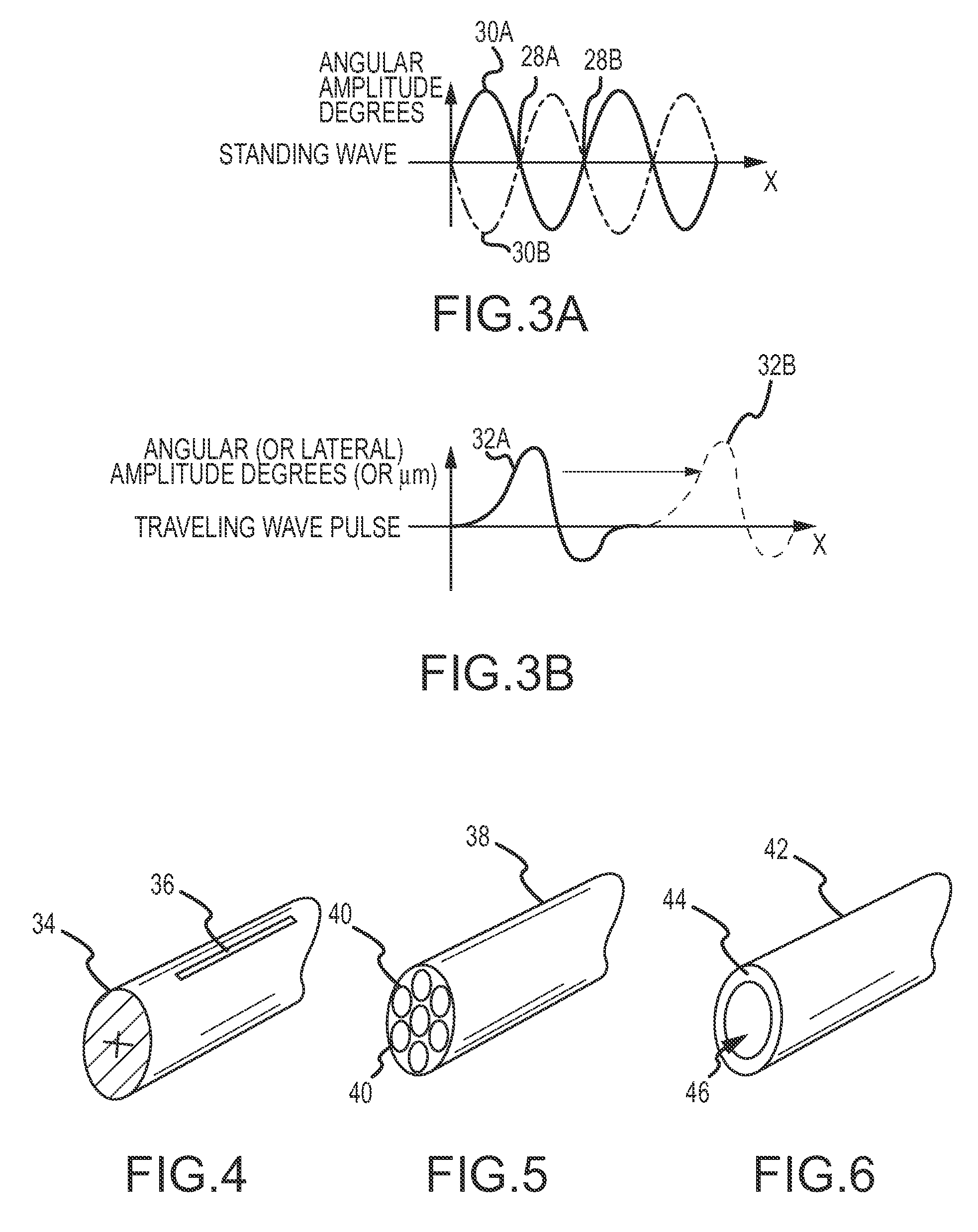
[0012]In a still further embodiment, the acoustic driver (and amplifying and / or matching section, if present) are configured to produce discrete acoustic wave pulses traveling down or along the flexible clearing member. Discrete means one or a few cycles or waveforms delivered at a time. These pulses, when temporally isolated and temporally spaced apart by an acoustic attenuation time-constant, will not produce standing waves. In particular, the acoustic driver is configured to produce temporally adjacent traveling wave pulses with at least an acoustic relaxation time in between each. The discrete pulses may be transverse (lateral) or torsional (rotational), or both. Note this pulsed transverse deflection versus torsional deflection

Problems solved by technology

Historically, conventional devices were incapable of the semi-invasive time efficient clearing of substantial lengths of lumen deposits in a reasonable time, if at all.
Such devices also have the propensity to cause lumen damage due to high balloon pressures (if they utilize balloons) and / or outright tip mechanical punctures of the lumen walls even if they do not utilize balloons.
Restenosis is also a problem when such tissue insult is delivered.
There are at least two issues with these wire-cleaning devices.
This damping bleeds off most of the cleaning energy rendering the rest of the wire vibrationally ineffective.
The lateral vibration mode is particularly subject to such damping.
The second issue is that such a device is subject to a certain amount of fatigue and that the large-displacement lateral or radial motions induce very high oscillatory wires stresses.
Although disposable wires are desirable for sanitary reasons, the fatigue described above increases the risk of a wire break during even a single use.

Method used


Image

  • Ultrasonic endovascular clearing device
  • Ultrasonic endovascular clearing device
  • Ultrasonic endovascular clearing device

Examples


Embodiment Construction

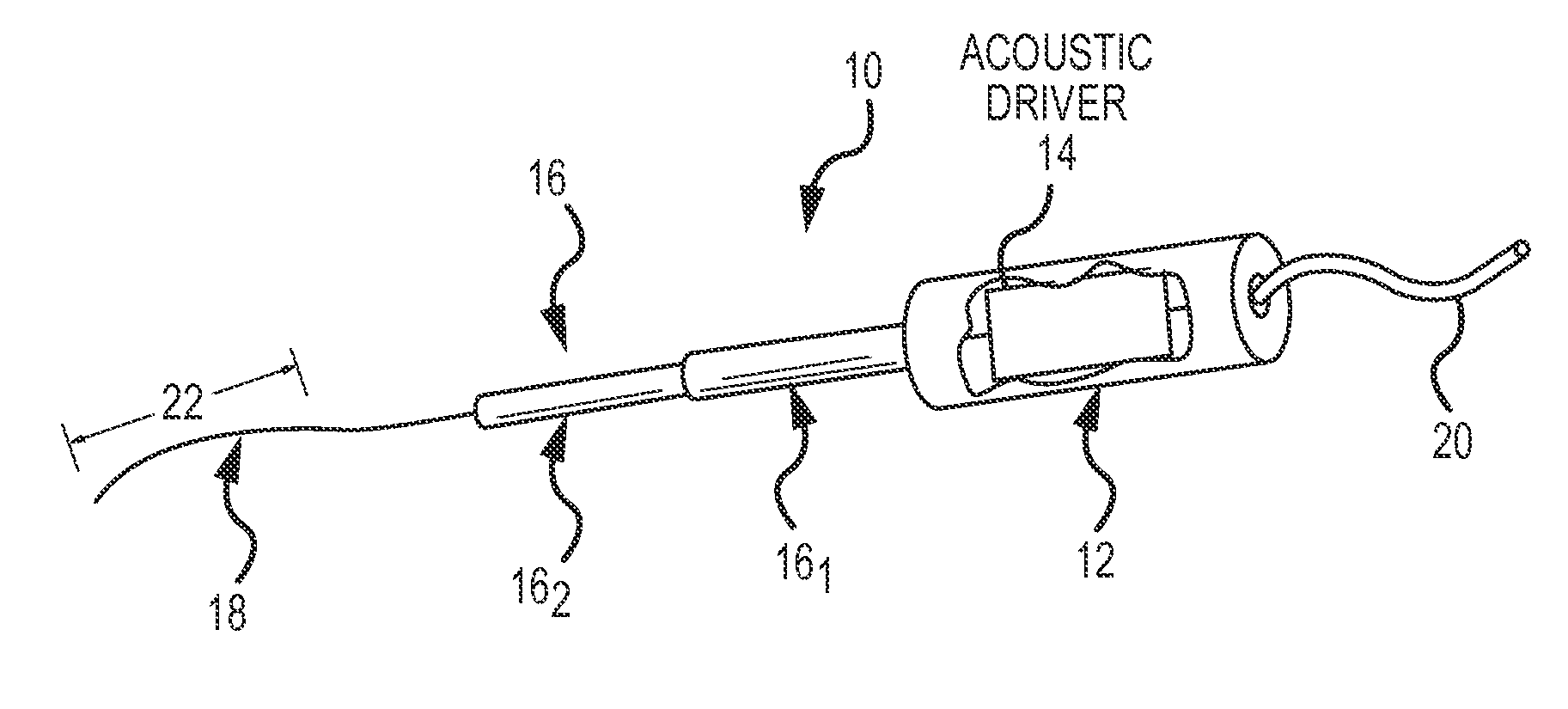
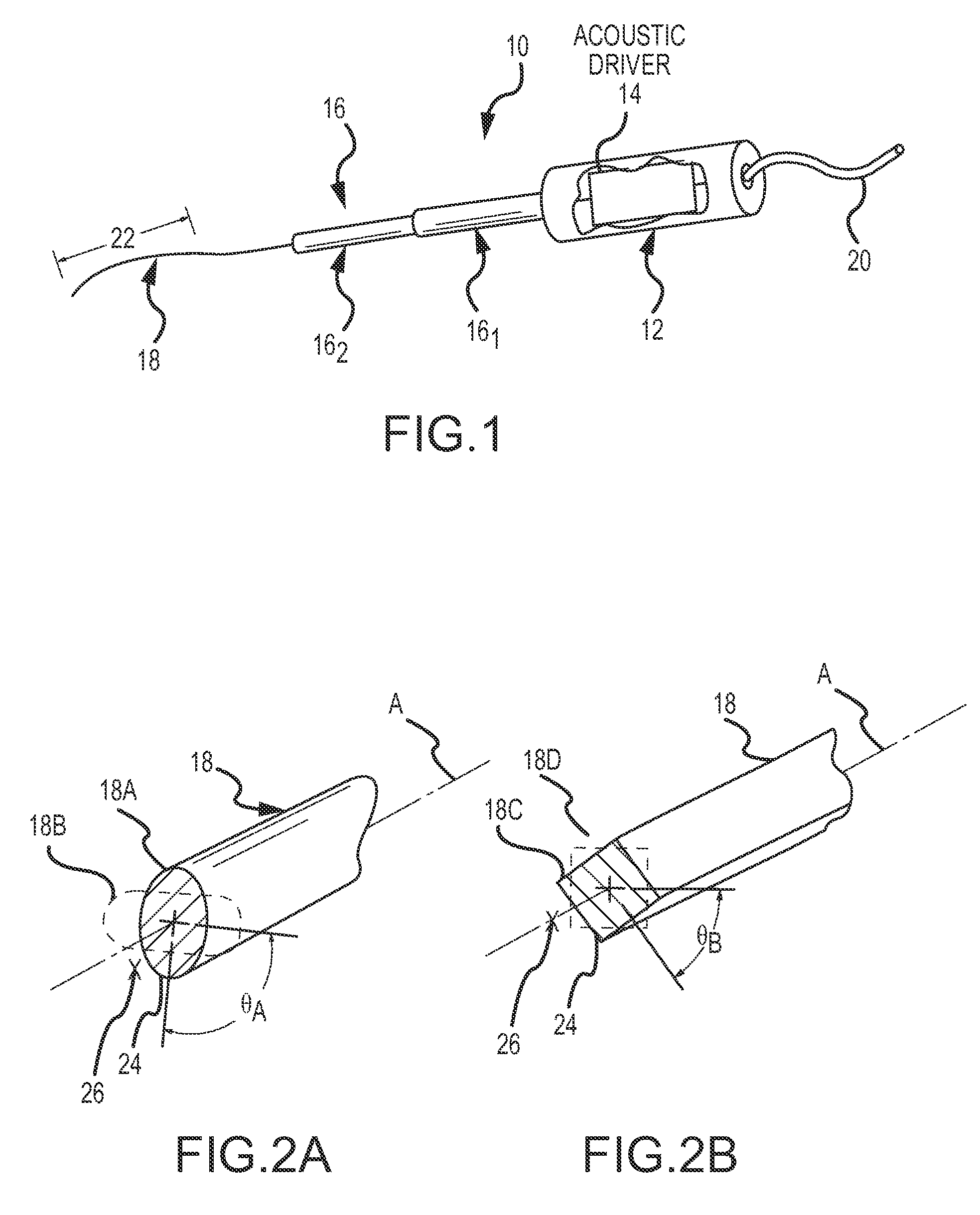
[0023]Referring now to the drawings wherein like reference numerals are used to identify identical components in the various views, FIG. 1 is a simplified, perspective view of an ultrasonic endovascular clearing medical apparatus 10 for use in a bodily lumen. Apparatus 10 is characterized by an acoustically driven flexible clearing member (e.g., the treating wire 18 shown), operating in the ultrasonic frequency range and having a plurality of operating modes, including modes that employ acoustically-driven torsional waves. However, before proceeding to a detailed description of the present invention keyed to the drawings, a general overview of the various modes of operation will be set forth.

[0024]In a first acoustic mode of operation, apparatus 10 is configured to acoustically rotate, in a torsional orientation, a flexible clearing member at an operating frequency and amplitude (e.g., degrees of rotational deflection) selected so as to produce rotational displacement nodes and anti...


PUM


Abstract

An ultrasonic endovascular clearing device for use in a bodily lumen includes a powering handle configured to enclose one or more acoustic drivers, an acoustic amplifier and / or acoustic matching section including one or more amplifiers and / or matching elements and a driven wire. The acoustic drivers are configured to produce acoustic vibration in the ultrasonic frequency range. The amplifier / matching section matches and amplifies the acoustic vibration and drives the wire accordingly. The wire cleans due to one or both of a) its asymmetric shape being driven, b) its feature-enhanced surface being driven, whether on an asymmetric wire or not. The driving is pulsed or continuous, cavitating or noncavitating, and torsional or radial / lateral in its possible operational embodiments. A drug may be used by or delivered by the device and wire / tissue parameter sensing is optionally provided.

Description

BACKGROUND OF THE INVENTION[0001]a. Field of the Invention[0002]The instant invention relates to an ultrasonic endovascular clearing device. In particular, the instant invention relates to an ultrasonic endovascular clearing device for clearing plaque, thrombosis and other blockages and / or restrictions in bodily lumens. Such lumens are typically natural lumens but may also include implanted lumens such as grafts and stents.[0003]b. Background Art[0004]It is known to employ various apparatus to clear fouled or blocked bodily lumens (e.g., blood vessels). Historically, conventional devices were incapable of the semi-invasive time efficient clearing of substantial lengths of lumen deposits in a reasonable time, if at all. For example, existing catheter-based devices perform their cleaning action only at their local tip position in the lumen. Such devices also have the propensity to cause lumen damage due to high balloon pressures (if they utilize balloons) and / or outright tip mechanica...

Claims


Application Information

Patent Timeline
Patent Type & Authority Patents(United States)
IPC IPC(8): A61B17/20
CPCA61B17/22012A61B2017/22015A61B2017/22017
Inventor SLIWA, JOHN, W.
Owner ST JUDE MEDICAL ATRIAL FIBRILLATION DIV
Learn More