
Network terminal identification

a network terminal and identification technology, applied in the field of identification or selection of network terminals, can solve the problems of inability to work within buildings, need for periodic polling of correspondents, etc., and achieve the effects of preventing manual overhead, reducing costs, and increasing updates accuracy

Inactive Publication Date: 2014-07-22
INT BUSINESS MASCH CORP
View PDF9 Cites 0 Cited by
  • Summary
  • Abstract
  • Description
  • Claims
  • Application Information

AI Technical Summary

Benefits of technology

[0018]The automatic creation and maintenance of identity groups prevents the manual overhead that would instead be required, thus reducing the cost and increasing updates accuracy.
[0019]Given the established identity group, the communication between the people that are logically close to each other will be much easier, reducing the need of broader message posting and therefore reducing the information traffic.

Problems solved by technology

The prior art approach of compiling a mailing list on the basis of geographical proximity determined on the basis of GPS data has a number of drawbacks, for example in view of the requirement for all correspondents to be equipped with GPS hardware, inherent disadvantages of GPS such as the inability to work within buildings and the need for periodic polling of the correspondents.
These drawbacks are particularly apparent in a case where correspondents to be added to a list are in close proximity, for example within the same building.

Method used


Image

  • Network terminal identification
  • Network terminal identification
  • Network terminal identification

Examples


first embodiment

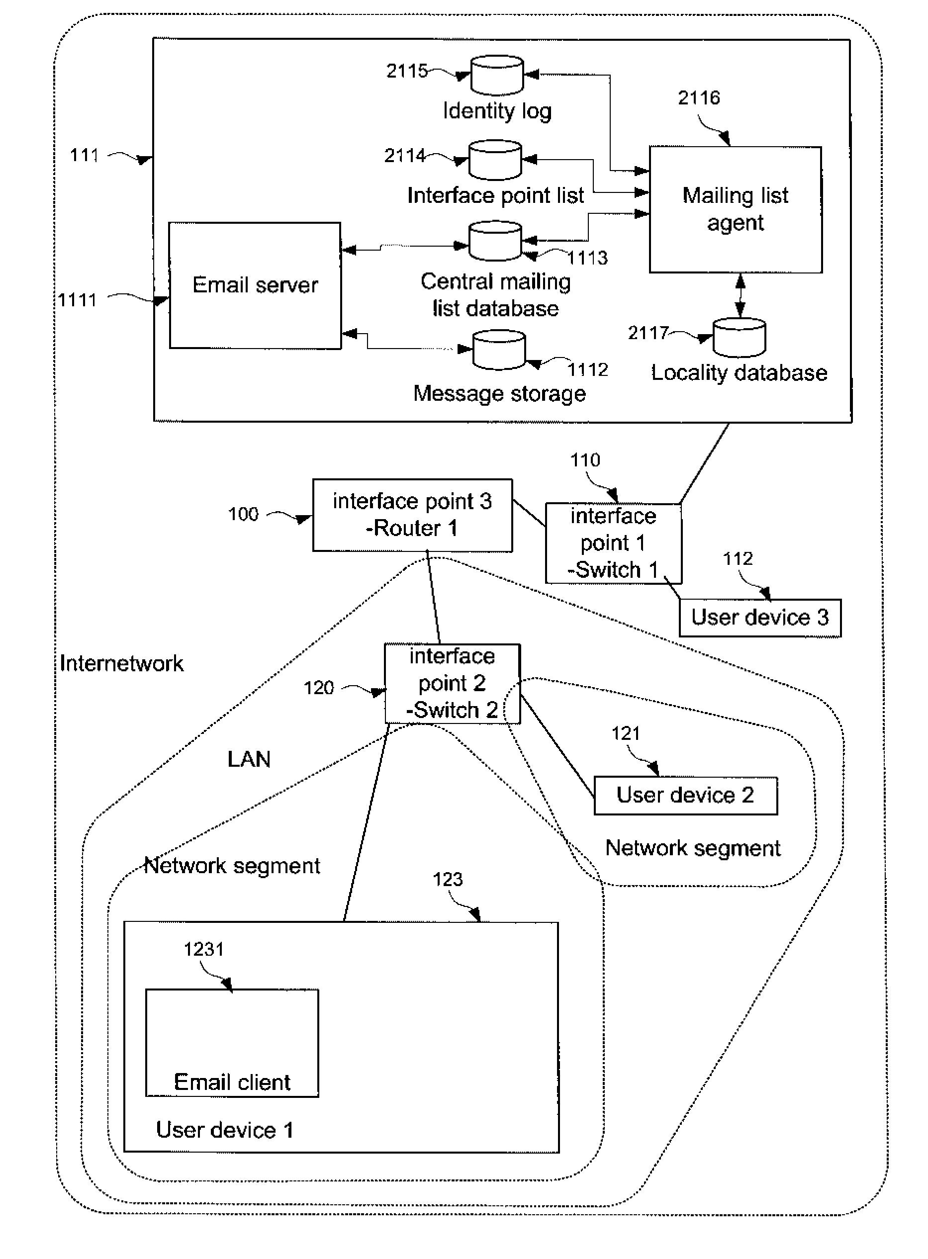
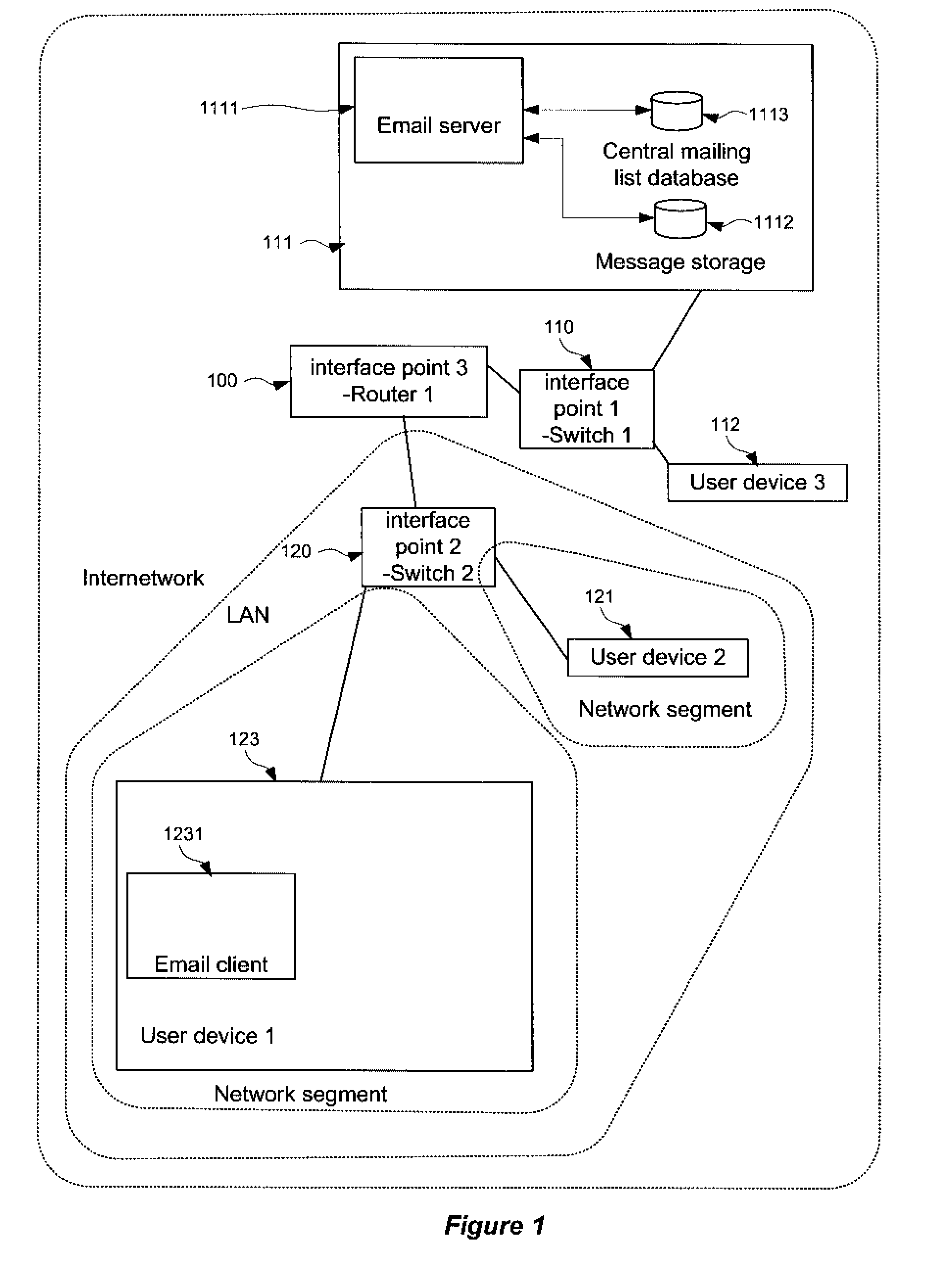
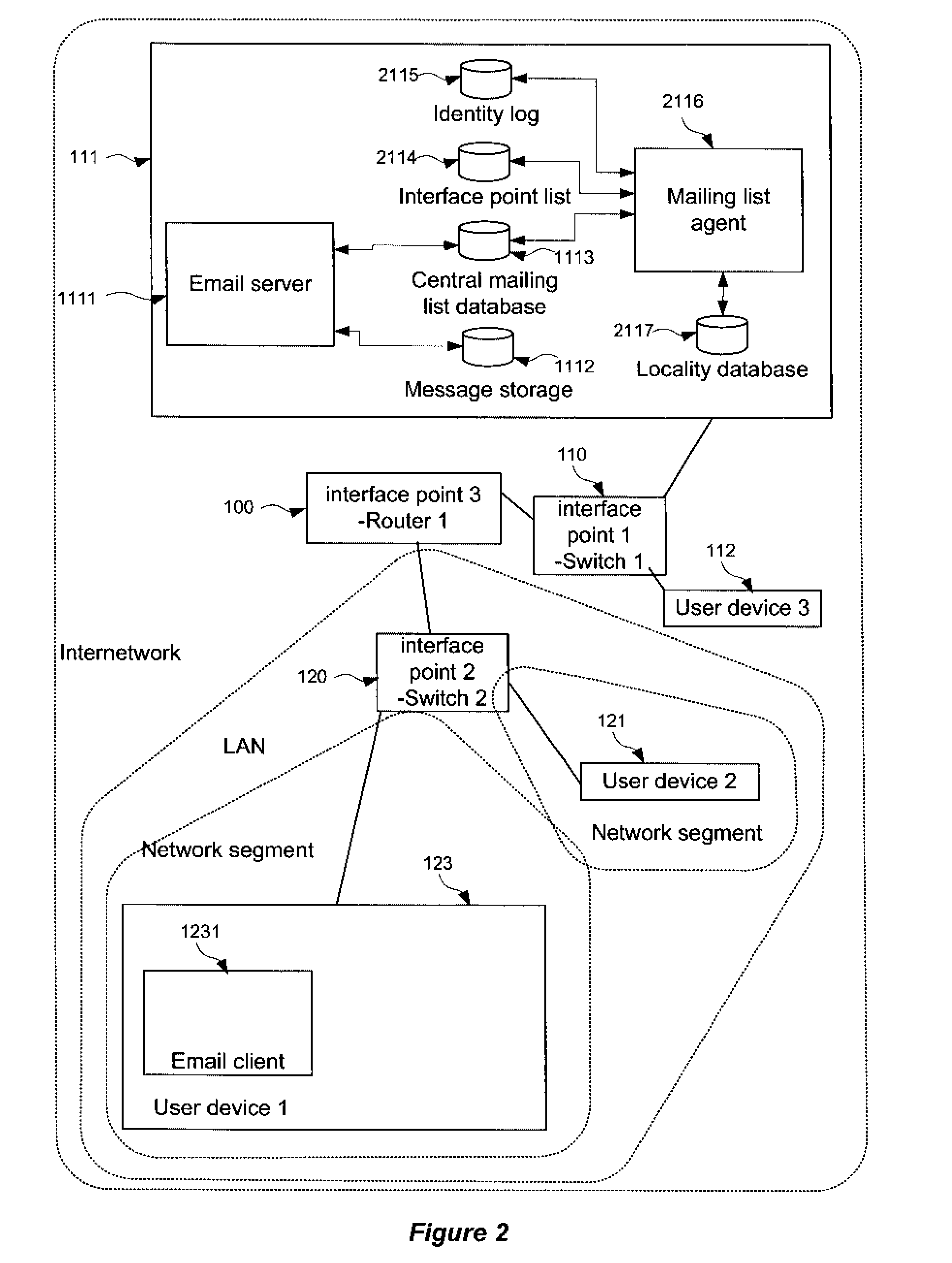
[0033]FIG. 2 shows a conventional computer network modified in accordance with the invention. FIG. 2 shows a network substantially as described above with respect to FIG. 1, with the server 111 additionally being provided with a mailing list agent 2116 in communication with an interface point list 2114 and an identity log 2115. The mailing list agent 2116 is furthermore in communication with the central mailing list database 1113.

[0034]The interface point list contains a list of uniquely identifiable interface points belonging to the network. The list uniquely identifies each interface point, by means for example of its IP address, MAC id, IMSI etc. and further notes the physical location of each of respective interface point. According to certain embodiments, the physical location may treated as being implicit from the interface point ID itself, and no further information provided. Otherwise, the list may be compiled manually, for example, by a system administrator, or it may advan...

second embodiment

[0092]FIG. 3 shows a conventional computer network modified in accordance with the invention. FIG. 3 shows a network substantially as described above with respect to FIG. 1, with the user device 123 additionally being provided with a mailing list agent 3216 in communication with an interface point list 3214 and an identity log 3215. The mailing list agent 3216 is furthermore in communication with the local mailing list database 3232 of the user device 123.

[0093]According to this second embodiment, the features described with respect to the first embodiment as performed by the mailing list agent 2116 are carried out by the mailing list agent 3216, that is, by processes running at the user device 123 requiring a custom mailing list. In such a case, the user device itself will be responsible for gathering and storing the requisite data from the network, and as such may still be considered as exhibiting server functionality. Such an approach may be particularly compatible with aspects o...


PUM


Abstract

A method of dynamically composing or updating electronic contact lists, such as mailing lists, on the basis of proximity to a particular point or user. By means of this method a user can be offered the option of addressing a method to all “nearby” users. Proximity may be determined with reference to network hardware or other resources associated with each user, for example, LAN segments or wireless access points.

Description

FIELD OF THE INVENTION[0001]The present invention relates to the identification or selection of network terminals, for example, as message destinations.BACKGROUND OF THE INVENTION[0002]The tools that modern information technology provides allow us to communicate with an ever increasing number of people. However, reaching those particular individuals in our immediate vicinity is often more difficult than it may appear at first sight.[0003]Consider, for example, the steps necessary to send an e-mail message to the individuals working on the same floor of the same building of an individual's office. Just remembering the names of all of the persons will be a problem.[0004]The prior art suggests certain peripherally related arrangements.[0005]As discussed in the article entitled Intelligent Addressing Capability for E-mail systems (ip.com reference IPCOM000028248D), users of electronic mail programs such as IBM's Lotus Notes or Microsoft Hotmail are accustomed to saving contacts in an ‘a...

Claims


Application Information

Patent Timeline
Patent Type & Authority Patents(United States)
IPC IPC(8): G06F15/173
CPCH04L12/58H04L12/1845H04L12/1886H04L12/24H04L41/00H04L51/28H04L67/18H04W4/02H04L51/48H04L67/52H04L51/00
Inventor PICHETTI, LUIGISECCHI, MARCOSECOMANDI, ANTONIO
Owner INT BUSINESS MASCH CORP
Learn More