
Touch integrated display device

a display device and integrated technology, applied in the field of touch display devices, can solve the problems of reduced visibility, increased thickness, and reduced thickness, and achieve the effect of improving touch performance and reducing the thickness of the display devi

Inactive Publication Date: 2014-07-29
LG DISPLAY CO LTD
View PDF10 Cites 23 Cited by
  • Summary
  • Abstract
  • Description
  • Claims
  • Application Information

AI Technical Summary

Benefits of technology

[0010]An aspect of this document is to provide a touch integrated display device which can reduce thickness of a display device and improve touch performance.

Problems solved by technology

However, in order to use the above input devices, the user should learn how to use the input devices and the quality thereof is not easily improved by causing inconvenience, such as a space necessary for installation thereof.
However, the add-on type has a structure in which the completed touch panel is mounted on the display device and has the problems, such as increased thickness or reduced visibility due to low brightness of the display device.
In addition, the on-cell type touch has a structure in which the touch panel is formed on an upper surface of the display device and can reduce the thickness in comparison with the add-on type but has the problems that the entire thickness is increased by a driving electrode layer, a sensing electrode layer, and an insulation layer for insulating the driving electrode layer and the sensing electrode layer and the increase of the entire thickness and the number of processes causes an increase in manufacturing costs.
In addition, the in-cell type can reduce thickness of the display device by forming elements constituting the touch panel in the inside of the display device but has the problem that a driving electrode and a sensing electrode for composing the touch panel cause wirings and parasitic capacitance of the display device and the touch recognition performance is thereby lowered.

Method used


Image

  • Touch integrated display device
  • Touch integrated display device
  • Touch integrated display device

Examples


first embodiment

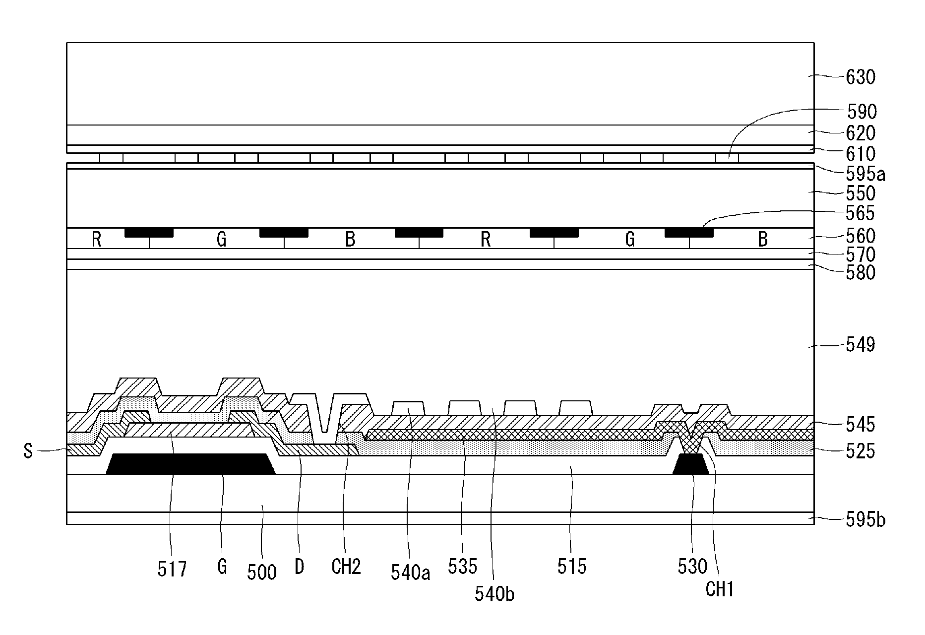
[0056]FIG. 4 is a view illustrating a touch integrated display device according to the present invention.

[0057]Referring to FIG. 4, in the touch integrated display device according to the first embodiment of the present invention, a gate electrode G and a common line 530 are positioned on a lower substrate 500, and a gate insulating layer 515 is positioned to insulate the gate electrode G from the common line 530. A semiconductor layer 517 is positioned on the gate insulating layer 515, and a source electrode S and a drain electrode D are respectively connected to two ends of the semiconductor layer 517. A first protective layer 525 is positioned on the lower substrate 500 including the source electrode S and the drain electrode D. A common electrode 535 is connected to the common line 530 through a first contact hole CH1 which penetrates the first protective layer 525 and the gate insulating layer 515. A second protective layer 545 is positioned on the common electrode 535. A pixel...

second embodiment

[0061]FIGS. 5A and 5B are views illustrating a touch integrated display device according to the present invention.

[0062]Referring to FIGS. 5A and 5B, in the touch integrated display device according to the second embodiment of the present invention, the driving electrodes 580 described in connection with FIG. 4 are not formed, and black matrixes 565 instead plays a role as the driving electrodes 580.

[0063]More specifically, referring to FIG. 5B, the black matrixes 565 are arranged in parallel to each other in an X-direction on the upper substrate 550 and R, G, and B, and color filters 560 are respectively positioned at sub-pixel regions. The black matrixes 565 are divided along a direction perpendicular to a longitudinal direction of the sub-pixel P, that is, a y-direction. For example, the black matrixes 565 are divided in a direction intersecting the sensing electrodes and include a metal material so that the black matrixes 565 play a role as the driving electrodes.

[0064]As such, ...

third embodiment

[0066]Referring to FIG. 6, the touch integrated display device according to the present invention includes the upper polarizer 595a attached on the upper surface of the upper substrate 550, an electrode film 610 positioned on the sensing electrodes 590, an adhesive 620 positioned on the electrode film 610, and a reinforcing glass plate 630 attached to the electrode film 610 through the adhesive 620.

[0067]According to an embodiment, the sensing electrodes 590 are formed on the electrode film 610. The electrode film 610 is attached on the upper substrate to which the upper polarizer 595a is attached. The adhesive 620 is formed on the upper substrate 550 to which the electrode film 610 is attached, and the reinforcing glass plate 630 is attached on the adhesive 620.


PUM

PropertyMeasurementUnit
electric fieldaaaaaaaaaa
thicknessaaaaaaaaaa
structuresaaaaaaaaaa

Abstract

The present invention provides a touch integrated display device which reduces a thickness of a display device and can improve touch performance. The touch integrated display device according to one embodiment of the present invention can include: a TFT positioned on a lower substrate; a pixel electrode connected to the TFT; a common electrode facing the pixel electrode to form electric field; a liquid crystal layer positioned on the common electrode; an upper substrate facing the lower substrate which is positioned at both sides of the liquid crystal layer; a driving electrode which is positioned on one side of the upper substrate adjacent to the liquid crystal layer; and a sensing electrode which is positioned on the other side of the upper substrate and faces the driving electrode.

Description

[0001]This application claims the benefit of Korean Patent Application No. 10-2011-0017176 filed on Feb. 25, 2011 which is hereby incorporated by referenceBACKGROUND[0002]1. Field[0003]This document relates to a touch display device, and more particularly to a touch integrated display device which can reduce thickness and improve touch performance.[0004]2. Description of the Related Art[0005]Various input devices, such as a keyboard, a mouse, a trackball, a joystick, a digitizer, and the like, are used for an interface between a user and home appliances or various information communication devices. However, in order to use the above input devices, the user should learn how to use the input devices and the quality thereof is not easily improved by causing inconvenience, such as a space necessary for installation thereof. Accordingly, a demand exists for input devices which have convenient and simple functions and can reduce malfunctions. In response, a touch panel has been proposed t...

Claims


Application Information

Patent Timeline
Patent Type & Authority Patents(United States)
IPC IPC(8): G02F1/1335G06F3/041
CPCG06F3/0412G02F1/13338G06F3/044G06F2203/04103G06F3/0445G06F3/0446G06F2203/04111
Inventor HWANG, SANGSOOKIM, CHEOLSEHAN, MANHYEOP
Owner LG DISPLAY CO LTD
Learn More