Method for imaging of nonlinear interaction scattering

a nonlinear interaction and scattering technology, applied in the field of nonlinear scattering imaging, can solve the problems of difficult to distinguish linear and linear signal components, material parameters also produce accumulative nonlinear distortion of forward propagating wave, and signal components are difficult to distinguish

Active Publication Date: 2014-07-29
SURF TECH AS
View PDF11 Cites 8 Cited by
  • Summary
  • Abstract
  • Description
  • Claims
  • Application Information

AI Technical Summary

Benefits of technology

[0016]Preferably the said transmitting step comprises transmitting a plurality of transmit events where the transmit time between said transmit events is sufficiently high that at least two different overlap regions propagate simultaneously within the object, and one or both of the relative timing between said 1st and 2nd transmit pulse and said 1st and 2nd transmit directions is varied between the transmit events so that said at least two different overlap regions propagate along at least two different measurement or image curves and the scattered signals from said different overlap regions are received and processed in parallel for improved rate of measurement or imaging.
[0018]Preferably the received signals from a plurality of transmit events for the same measurement or image curves Γ(r) are averaged to reduce noise and improve sensitivity.
[0041]The methods and instrumentation are applicable for imaging of nonlinear material parameters both for electromagnetic and elastic waves and combinations of these. 1st and 2nd pulsed waves are transmitted along 1st and 2nd transmit beams where in preferred embodiments at least one of the beams is broad in at least one direction. The transmit timing between said 1st and 2nd pulsed waves is selected so that the wave pulses overlap in an overlap region R(r,t) that propagates along a measurement or image curve Γ(r) in the object. At least the scattered signal produced by nonlinear interaction scattering between said 1st and 2nd waves in the overlap region is received and processed to form nonlinear interaction scattering image signal(s) along Γ(r). The measurement or image curve Γ(r) may be scanned laterally in two or three dimensions by either changing of the relative transmit timing between the 1st and 2nd pulsed waves or the direction of the 1st and 2nd transmit beams, or both, to form two-dimensional or three-dimensional images of the object. The methods enhance measurement or imaging of scatterers that are either much softer or much harder than the surrounding medium, and are for example useful for, but not limited to, imaging of micro-calcifications and contrast agent gas micro-bubbles in medical imaging, hard structures like mines in the soil, gas bubble formation in the blood of divers, and swim bladders of fish and the like in water.

Problems solved by technology

However, the nonlinear variation of the material parameters also produces an accumulative nonlinear distortion of the forward propagating wave.
When the pulse length of the high frequency pulse increases above approximately a half period of the low frequency pulse, the linear scattering from the nonlinear forward propagation distortion has a similar signature to the local nonlinear scattering, and it is in this case difficult to distinguish the signal components that occur from linear scattering of the nonlinear propagation distortion of the incident wave, and the signal components that occur from local nonlinear scattering.

Method used


Image

  • Method for imaging of nonlinear interaction scattering
  • Method for imaging of nonlinear interaction scattering
  • Method for imaging of nonlinear interaction scattering

Examples


Embodiment Construction

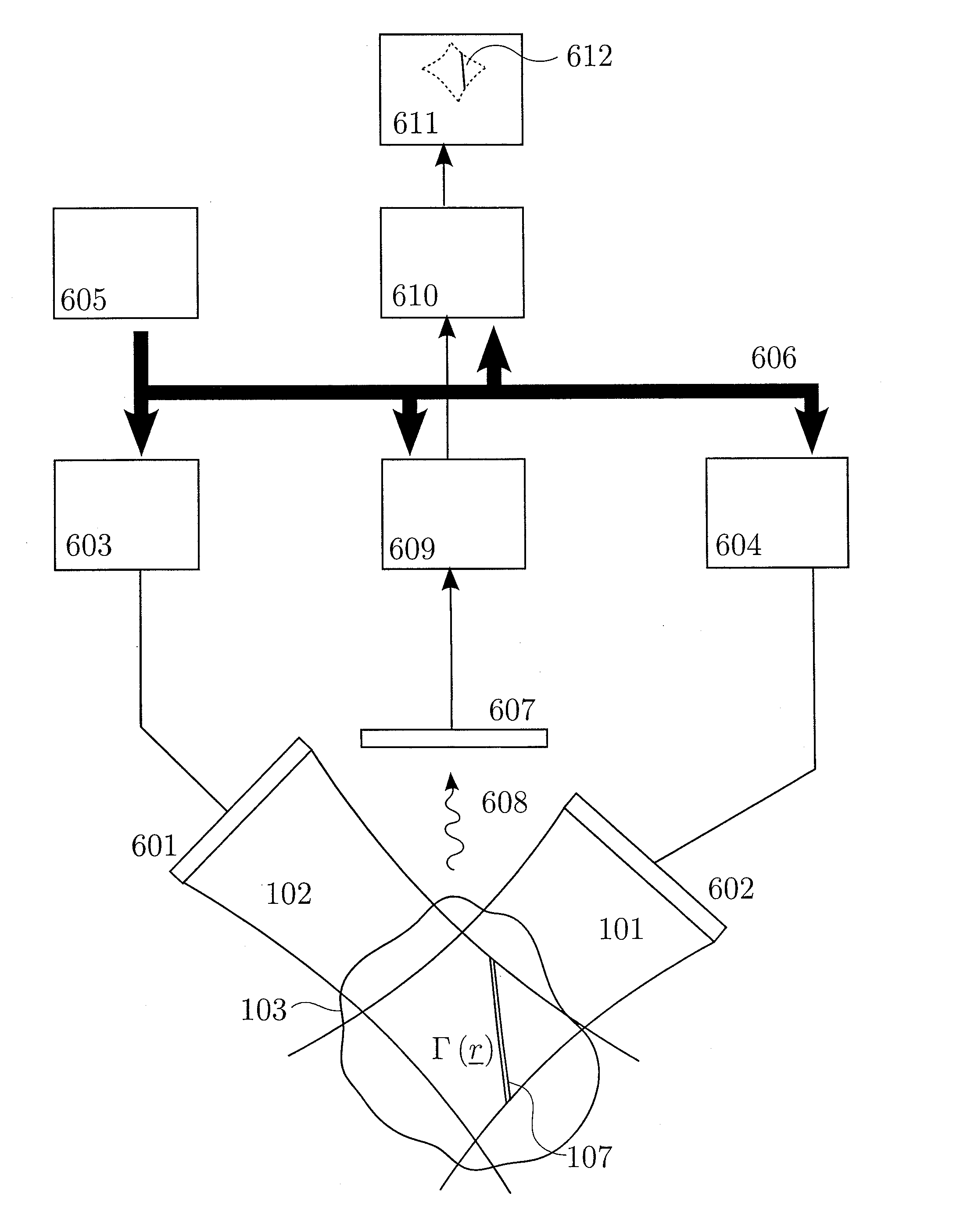
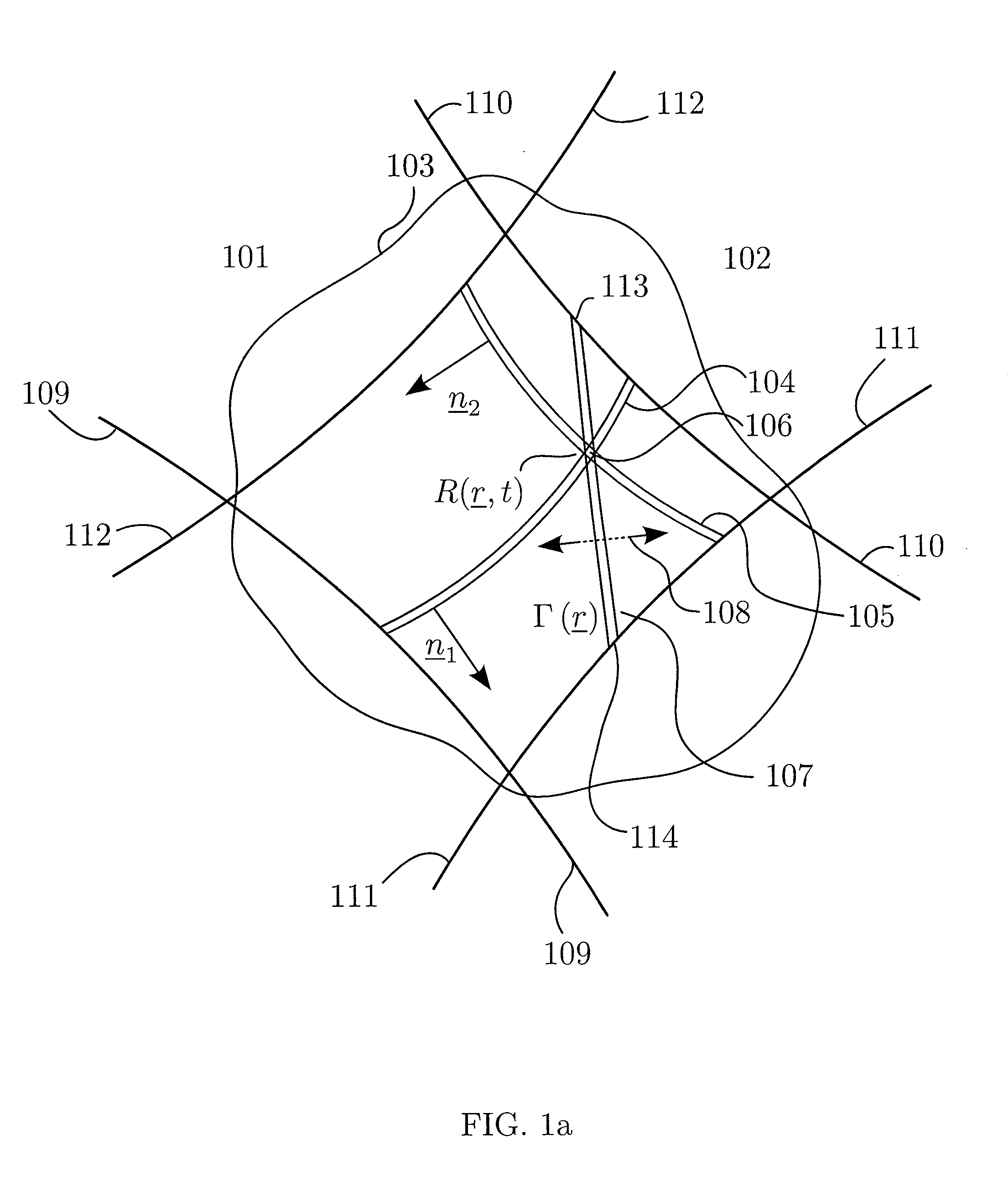
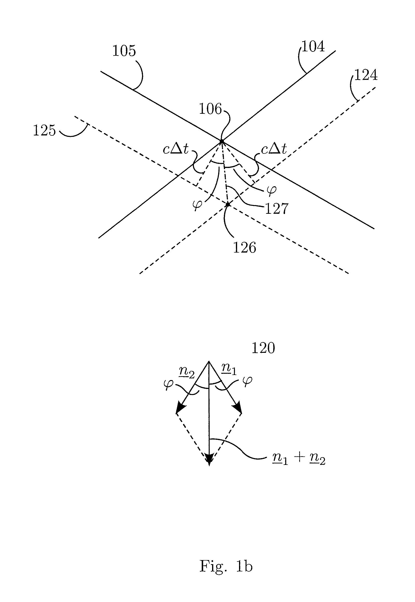
[0056]In FIG. 1a is shown a 1st pulsed wave beam 101, bounded by the lines 109 and 110, and a 2nd pulsed wave beam 102, bounded by the lines 111 and 112, where both 1st and 2nd beams are incident onto an object 103. In this example both beams are wide in the azimuth plane, which is the paper plane, but would preferably in this example be narrow in the elevation direction normal to the azimuth plane. An embodiment where one of the beams is narrow where the other beam is wide in the azimuth direction, is shown in FIG. 10. Continuing with FIG. 1, 104 designates a 1st pulsed wave field that propagates along the 1st beam, with a unit normal n1(r) to the pulsed wave front, where r is the coordinate vector in 3D space of combined azimuth and elevation directions. A 2nd pulsed wave field 105 propagates along the 2nd beam, with a unit normal n2(r) to the pulsed wave front. The 1st and 2nd pulsed waves have 1st and 2nd center frequencies ω1=2πf1 and ω2=2πf2 and can for example be expressed wi...


PUM


Abstract

1st and 2nd pulsed waves are transmitted along 1st and 2nd transmit beams where at least one of the beams is broad in at least one direction, and the transmit timing between said 1st and 2nd pulsed waves are selected so that the pulsed wave fronts overlap in an overlap region R(r,t) that propagates along at least one measurement or image curve Γ(r) in the material object. At least the scattered signal produced by nonlinear interaction between said 1st and 2nd waves in the overlap region is received and processed to form a nonlinear interaction scattering image signal along Γ(r). The measurement or image curve Γ(r) can be scanned laterally by either changing of the relative transmit timing between the 1st and 2nd pulsed waves or the direction of at least one of the 1st and 2nd transmit beams, or both. The methods are applicable to image nonlinear scattering sources for both electromagnetic and elastic waves, and combinations of these.

Description

CROSS-REFERENCE TO RELATED APPLICATIONS[0001]This is a U.S. Utility application based on U.S. Provisional Application No. 61 / 375,403, filed Aug. 20, 2010. Priority is claimed on GB Application No. 1018933.0, filed Nov. 9, 2010, the contents of which are incorporated herein by reference in its entirety.FIELD OF THE INVENTION[0002]The present invention addresses imaging of nonlinear scattering with elastic and electromagnetic waves and combinations of these. It has applications both in medical and technical fields.BACKGROUND OF THE INVENTION[0003]Material properties for both electromagnetic (EM) and elastic (EL) waves often show nonlinear properties where the material parameters depend on the amplitude of the field variables of the waves. Spatial variation in nonlinear material properties provide nonlinear scattering of both EM and EL waves, and imaging of such nonlinear scattering sources are in many situations useful to identify material properties. Both the forward wave propagation...

Claims


Application Information

Patent Timeline
Patent Type & Authority Patents(United States)
IPC IPC(8): G06F19/00
CPCG01S7/52038G01S7/52077G01S15/8952G01V99/005G01N21/49G01N29/04G01N29/0654G01S15/89G01S15/96G01V1/24
Inventor ANGELSEN, BJORN A. J.HANSEN, RUNETANGEN, THOR ANDREAS
Owner SURF TECH AS
Why Eureka
Try Eureka