Linear compressor

a compressor and linear technology, applied in the direction of positive displacement liquid engines, pumping machines, machines/engines, etc., can solve the problems of increasing unit costs and overall costs of production, reducing the size of peripheral components, and difficult to employ a cylindrical magnet, so as to improve the efficiency of the whole system, reduce production costs, and simplify the effect of controlling

Active Publication Date: 2014-08-05
LG ELECTRONICS INC
View PDF26 Cites 7 Cited by
  • Summary
  • Abstract
  • Description
  • Claims
  • Application Information

AI Technical Summary

Benefits of technology

[0035]According to the present invention, since the linear motor employs the conductor member instead of the magnet to supply a driving force by magnetic induction, the mechanism and controlling thereof are simplified, so that the costs of production are cut down. Moreover, since the linear motor can be driven by minimum elements without a special driving unit for controlling, it is possible to improve entire efficiency.
[0036]In addition, according to the present invention, the linear motor is not affected by variations of externally-applied power, and varies a stroke to automatically or naturally modulate a cooling capacity according to a load without adopting a special control method. It is thus possible to maximize cooling efficiency.

Problems solved by technology

However, it is difficult to employ a cylindrical magnet because of a high price of the magnet.
Even if several bar-shaped magnets are fixed to form a magnet frame, the unit costs and overall costs of production still increase.
To this end, a complicated control unit is provided, which is accompanied with design limitations on sizes of peripheral components.
Further, a complicated control method is required, which increases the costs of production and complicates a manufacturing process.
Furthermore, much power is consumed for controlling, which degrades efficiency of the whole compressor.

Method used


Image

  • Linear compressor
  • Linear compressor
  • Linear compressor

Examples


Embodiment Construction

[0049]Hereinafter, the present invention will be described in detail with reference to embodiments and drawings.

[0050]FIGS. 3 to 5 are side-sectional views illustrating various embodiments of a linear compressor according to the present invention.

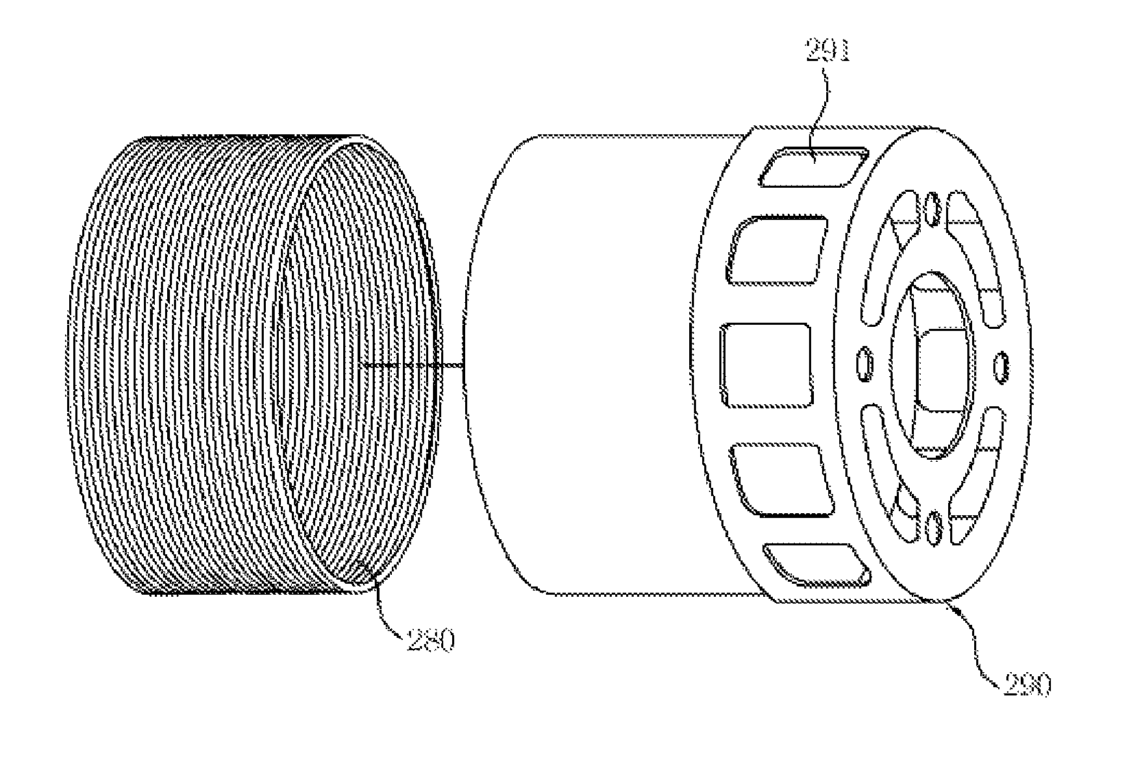
[0051]As illustrated in FIGS. 3 to 5, the linear compressor according to the present invention is constructed such that a fixed member 120 provided with a compression space P of refrigerant, a movable member 130 compressing refrigerant in the fixed member 120, and a linear motor 200 driving the movable member 130 are installed in a hermetic container 100. The linear motor 200 includes first and second stators 220 and 240, and a conductor member 260 positioned in a space between the first and second stators 220 and 240.

[0052]The second stator 240 is fixed to an outer circumference of the fixed member 120, and the first stator 220 is fixed in an axial direction by a frame 110 and a motor cover 300. Since the frame 110 and the motor cover 300 ...


PUM


Abstract

A linear compressor for producing a driving force by magnetic induction and naturally modulating a cooling capacity according to a load includes a fixed member provided with a compression space, a movable member which linearly reciprocates inside the fixed member to compress refrigerant, a plurality of springs installed to elastically support the movable member in a motion direction, a first stator through which a current flows, a conductor member magnetically induced by the first stator to make the movable member linearly reciprocate, and a control unit which controls supply of a current with respect to the first stator.

Description

[0001]This application is a 35 U.S.C. §371 National Stage entry of International Application No. PCT / KR2009 / 004237, filed on Aug. 3, 2009, which claims the benefit of the earlier filing date and right of priority to Korean Application No. 10-2008-0076701, filed Aug. 5, 2008, the contents of which are hereby incorporated by reference herein in their entirety.TECHNICAL FIELD[0002]The present invention relates to a linear compressor, and more particularly to, a linear compressor which employs a conductor member in a linear motor instead of a magnet to produce a driving force by magnetic induction and naturally modulate a cooling capacity according to a load.BACKGROUND ART[0003]In general, a compressor is a mechanical apparatus receiving power from a power generation apparatus such as an electric motor, a turbine or the like, and compressing the air, refrigerant or various operation gases to raise a pressure. The compressor has been widely used for electric home appliances such as refri...

Claims


Application Information

Patent Timeline
Patent Type & Authority Patents(United States)
IPC IPC(8): F04B35/04F04B17/04H02K33/02H02K33/04H02K33/12H02P25/06
CPCF04B35/045H02K33/04H02K33/02H02P25/06F04B17/04F04B35/04H02P25/062
Inventor KANG, KYE-LYONGKIM, JONG-KWONPARK, SHIN-HYUNKIM, HYUNKANG, HEE-DONGLEE, JEONG-UKJUNG, YANG-HOON
Owner LG ELECTRONICS INC
Why Eureka
Try Eureka