Symmetric thermocentric flexure with minimal yaw error motion

a thermocentric flexure and motion-free technology, applied in the field of optomechanical systems and nanomanufacturing, can solve the problems of poor pattern replication from the stamp to the part, surface distortion and warpage, etc., and achieve the effect of minimizing the error yaw motion (z) and minimizing the error yaw motion (z)

Active Publication Date: 2014-08-05
MASSACHUSETTS INST OF TECH
View PDF18 Cites 2 Cited by
  • Summary
  • Abstract
  • Description
  • Claims
  • Application Information

AI Technical Summary

Benefits of technology

[0005]According to one aspect of the invention, there is provided a stamping structure for imprinting micro-sized features. The stamping structure includes one or more optical flats. A flexure arrangement includes a plurality of beam flexures arranged in a symmetric configuration around the one or more optical flats so as to minimize the error yaw motion (θz) from thermal fluctuations associated with fixturing the one or more optical flats.
[0006]According to another aspect of the invention, there is provided a method of forming a stamping structure for imprinting micro-sized features. The method includes providing one or more optical flats. Also, the method includes arranging in a symmetric fashion around the one or more optical flat structures a plurality of beam flexures so as to minimize the error yaw motion (θz) from thermal fluctuations associated with fixturing the one or more optical flats.

Problems solved by technology

A mismatch in the thermal coefficients of expansion of such flats and the rest of the supporting structure (made usually from metal) may result in surface distortions and warping, and hence, poor pattern replication from the stamp to the part.

Method used


Image

  • Symmetric thermocentric flexure with minimal yaw error motion
  • Symmetric thermocentric flexure with minimal yaw error motion
  • Symmetric thermocentric flexure with minimal yaw error motion

Examples


Embodiment Construction

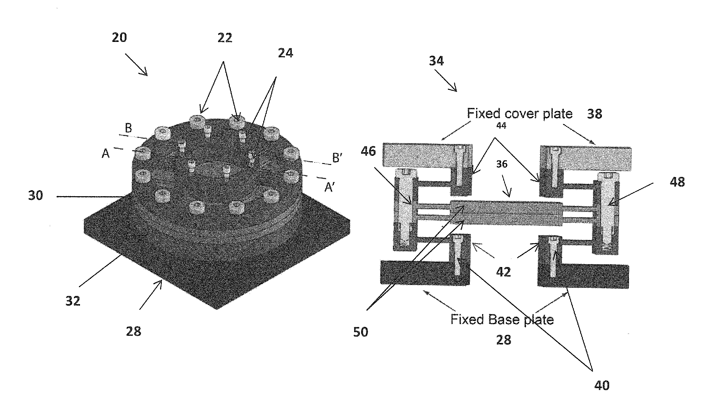
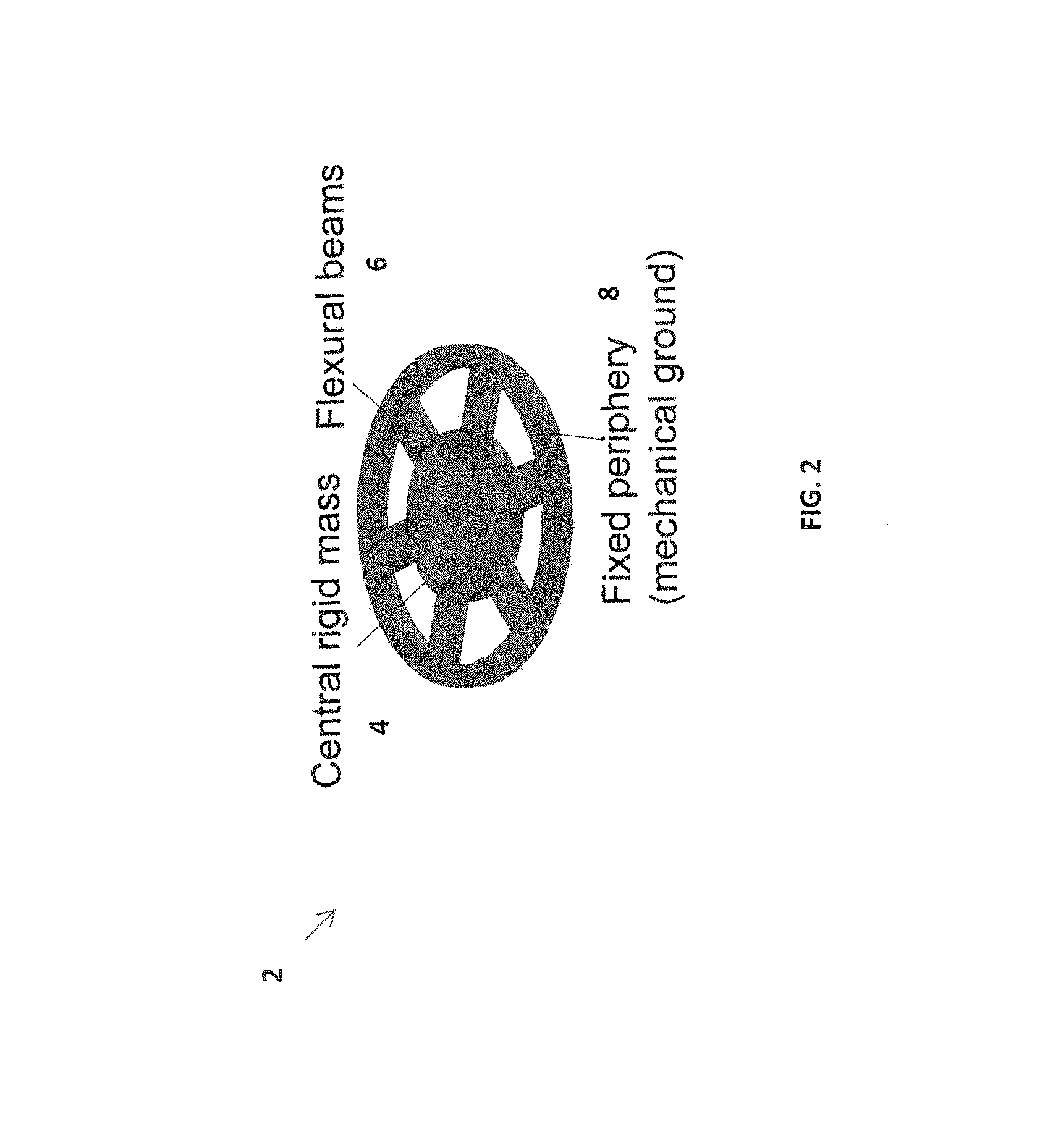
[0013]The invention provides a design and control of flexure-based mechanisms for positioning / fixturing and angular alignment for (i) pattern transfer via stamping and (ii) small-scale gap applications in micro / nanomanufacturing. As will be explained hereinafter, existing designs do not address some critical functional requirements identified for the applications of interest. The invention works toward new concepts and designs that one can implement and test.

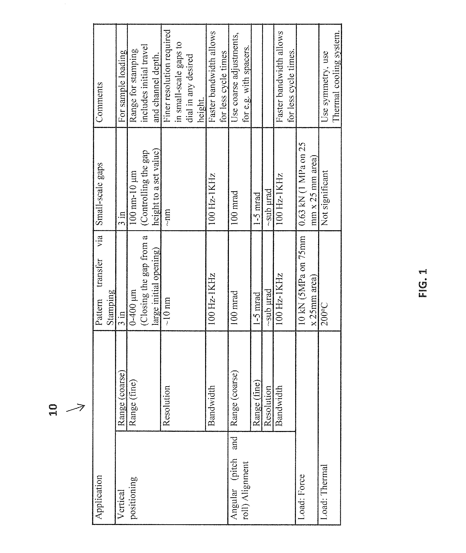
[0014]The invention focuses in positioning and aligning a tool and sample, or two optical flats, in their degrees of freedom (DOF) (z vertical, θx pitch and θy roll) while satisfying the following functional requirements given in Table 10 of FIG. 1. The constrained motions are x (lateral), y (lateral), and θz (yaw). Moreover, the invention uses parallel kinematics with actuator isolation, minimal cross-axis motion errors (e.g. errors in θx or θy when z is actuated), and minimal parasitic error motions (e.g. errors in x when z is...


PUM

PropertyMeasurementUnit
Ra roughnessaaaaaaaaaa
frictionaaaaaaaaaa

Abstract

A stamping structure for imprinting micro-sized features is provided. The stamping structure includes one or more optical flats. A flexure arrangement includes a plurality of beam flexures arranged in a symmetric configuration around the one or more optical flats so as to minimize the error yaw motion (θz) from thermal fluctuations associated with fixturing the one or more optical flats.

Description

PRIORITY INFORMATION[0001]This application claims priority from provisional application Ser. No. 61 / 045,694 filed on Apr. 17, 2008, and provisional application Ser. No. 61 / 049,789 filed on May 2, 2008, both of which are incorporated herein by reference in their entireties.BACKGROUND OF THE INVENTION[0002]The invention is related to the field of optomechanical systems and nanomanufacturing, and in particular to symmetric thermocentric flexures with minimal yaw error motion.[0003]Distortion-free fixturing of optical flats is critical to many micro / nano manufacturing applications. Optical flats are used, for example, as a rigid backing for stamps or polymer parts in microcontact printing and nano-imprint lithography. Other uses are in programmable small-scale gap applications, such as those involving stamping of DNA patterns assembled on one optical flat to another flat positioned in close proximity.[0004]Optical flats are made usually from fused silica or quartz, which have a coeffici...

Claims


Application Information

Patent Timeline
Patent Type & Authority Patents(United States)
IPC IPC(8): B29C59/00
CPCG03F7/0002B82Y10/00B82Y40/00Y10T29/49826
Inventor SHILPIEKANDULA, VIJAYYOUCEF-TOUMI, KAMAL
Owner MASSACHUSETTS INST OF TECH
Why Eureka
Try Eureka