Method of improving print performance in flexographic printing plates

a printing plate and relief image technology, applied in the field of relief image printing elements, can solve the problems of difficult to print small graphic elements such as fine dots, lines and even text, and easy damage to the press, and achieve the effect of good surface cur

Active Publication Date: 2014-08-05
MACDERMID PRINTING SOLUTIONS
View PDF41 Cites 0 Cited by
  • Summary
  • Abstract
  • Description
  • Claims
  • Application Information

AI Technical Summary

Benefits of technology

[0028]It is another object of the present invention to control the surface roughness of the print surface of the relief image printing element.
[0029]It is another object of the present invention to obtain well-defined dot shapes and thoroughly cured solid surface by achieving good surface cure of flexographic printing elements that are imaged using a direct write technology.
[0031]It is still another object of the present invention to provide an improved means of controlling the surface roughness of the print surface of the relief image printing element.

Problems solved by technology

It is very difficult to print small graphic elements such as fine dots, lines and even text using flexographic printing plates while maintaining open reverse text and shadows.
Maintaining small dots on flexographic plates can be very difficult due to the nature of the platemaking process.
The smallest of these dots are prone to being removed during processing, which means no ink is transferred to these areas during printing (the dot is not “held” on plate and / or on press).
Alternatively, if the dot survives processing they are susceptible to damage on press.
For example small dots often fold over and / or partially break off during printing causing either excess ink or no ink to be transferred.
A noted drawback to this method is that it is inconvenient and cumbersome and requires a large space for the apparatus.
However, the pre-sensitization step can also cause shadow tones to fill in, thereby reducing the tonal range of the halftones in the image.
In addition, if the photosensitive resin layer has a thickness of more than 0.1 mm, the weak light of the low intensity bump exposure dose does not sufficiently reach certain portions of the photosensitive resin layer (i.e., the side of the photosensitive layer that is closest to the substrate layer and furthest from the source of actinic radiation), at which the removal of the dissolved oxygen is insufficient.
In the subsequent main exposure, these portions will not cure sufficiently due to the remaining oxygen.
Unfortunately, these dyes are weak initiators and require protracted bump exposure times. In addition, these dyes sensitize the resin to regular room light, so inconvenient yellow safety light is required in the work environment.
Lastly, the approach described by Kawaguchi employs conventional broadband-type sources of actinic radiation light for bump exposure, and thereby also tends to leave significant amounts of oxygen in the lower layers of the resin.
In addition, one of the problems associated with direct write / laser engraving technology is that atmospheric oxygen inhibits the curing reaction at the surface, which results in poor curing in the outermost layer of photoresin.
This is manifested by large differences between the target (file) dot size and the resulting imaged dot size, scan line artifacts in the plate surface after imaging, and unacceptably high surface roughness after thermal processing.
However, this increases raw materials costs and / or creates additional procedures in the work flow that may introduce sources of variations in quality and thus require additional quality control.
A noted drawback to this method is that it is inconvenient and cumbersome and requires a large space for the apparatus.

Method used


Image

  • Method of improving print performance in flexographic printing plates
  • Method of improving print performance in flexographic printing plates
  • Method of improving print performance in flexographic printing plates

Examples


example

[0069]A direct write photoresin, comprising a crosslinkable elastomeric compound, a plasticizing compound, monomeric binder compounds, and a set of one or more photoinitiator compounds was utilized to demonstrate the advantages realized by the present invention.

[0070]The imaging process was conducted using a Lüscher Xpose! direct write laser at a power of 95 mW / cm2, a laser scanning speed of 550 rpm, with six scans made in a multi-pass imaging protocol with dot areas of 70%, 15%, and 1%, 1%, 1% and 1% on successive passes.

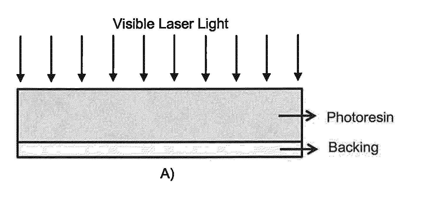
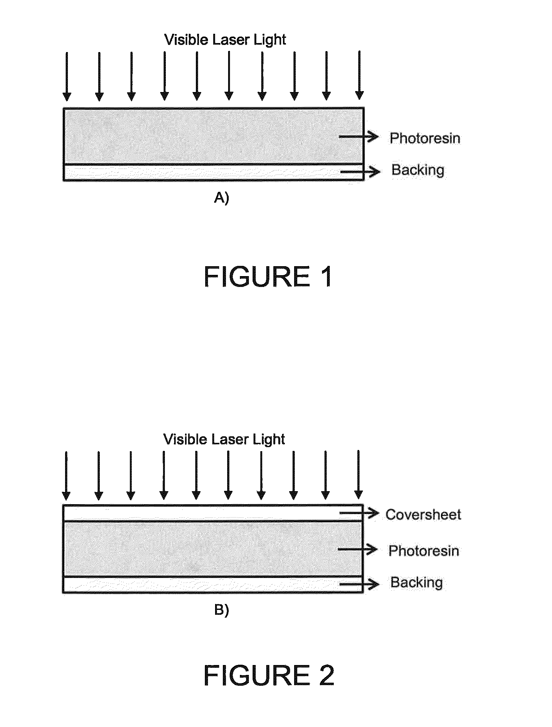
[0071]The imaging process was conducted using two different methods. In the first method, the imaging was conducted with the coversheet removed as a comparative example. In the second method, which is in accordance with the present invention, the imaging was conducted with the coversheet remaining on the photoresin during the imaging step.

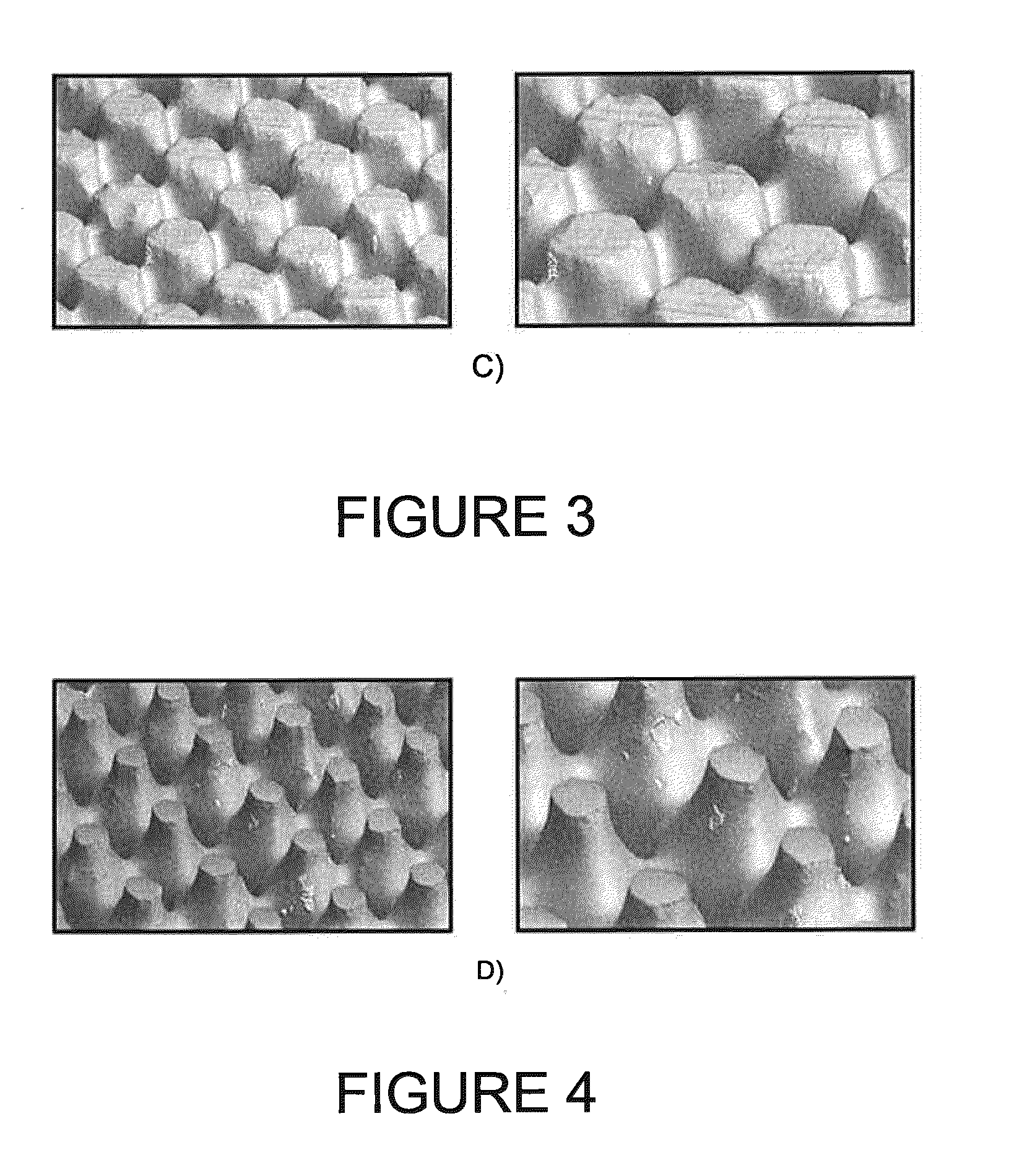
[0072]The resulting dot geometries obtained from these two methods are very different as shown in FIGS. 3-5.

[0073]FIG. 3 depicts...


PUM

PropertyMeasurementUnit
wavelengthaaaaaaaaaa
surface roughnessaaaaaaaaaa
thicknessaaaaaaaaaa

Abstract

A method of making a relief image printing element from a photosensitive printing blank is provided. The method comprising the steps of: 1) providing a photosensitive printing blank comprising a backing layer, at least one layer of photoresin on top of the backing layer and a removable coversheet on top of the at least one layer of photoresin; 2) imaging the photosensitive printing blank through the removable coversheet using a laser to create a relief image therein; and 3) removing the removable coversheet.

Description

FIELD OF THE INVENTION[0001]The present invention relates generally to a method of imaging a relief image printing element to provide an improved relief structure thereon.BACKGROUND OF THE INVENTION[0002]Flexography is a method of printing that is commonly used for high-volume runs. Flexography is employed for printing on a variety of substrates such as paper, paperboard stock, corrugated board, films, foils and laminates. Newspapers and grocery bags are prominent examples. Coarse surfaces and stretch films can be economically printed only by means of flexography. Flexographic printing plates are relief plates with image elements raised above open areas. Generally, the plate is somewhat soft, and flexible enough to wrap around a printing cylinder, and durable enough to print over a million copies. Such plates offer a number of advantages to the printer, based chiefly on their durability and the ease with which they can be made.[0003]A typical flexographic printing plate as delivered...

Claims


Application Information

Patent Timeline
Patent Type & Authority Patents(United States)
IPC IPC(8): B41N1/00G03F7/26B41M5/00G03F7/00
CPCG03F7/092G03F7/11G03F7/24G03F7/2002
Inventor CHOI, JONGHANBOUKAFTANE, CHOUAIBO'BRATE, KERRY
Owner MACDERMID PRINTING SOLUTIONS
Why Eureka
Try Eureka