Supercharge Your Innovation With Domain-Expert AI Agents!

Wind turbine with a primary and a secondary generator and method of operating such wind turbine

a secondary generator and wind turbine technology, applied in wind energy generation, motors, dynamo-electric machines, etc., can solve the problems of increasing the complexity and number of components of power converters, affecting the operation, and high cost of permanent magnet generators, so as to extend the usability of existing wind turbines, easy control and reliable

Inactive Publication Date: 2014-08-05
ENVISION ENERGY DENMARK
View PDF16 Cites 4 Cited by
  • Summary
  • Abstract
  • Description
  • Claims
  • Application Information

AI Technical Summary

Benefits of technology

The configuration enhances efficiency and cost-effectiveness by enabling high power output at both low and high wind speeds, reducing mechanical and electrical spikes, and extending the operational range of wind turbines above 1 MW, while minimizing component complexity and costs.

Problems solved by technology

This configuration has the drawback that it requires the use of two different generator sides each designed to match the power range of a particular generator type.
This in turn increases the complexity and number of components of the power converter.
This configuration does not provide means for a smooth transition when the DFIG generator is switched in which may introduce power or moment spikes in the drive train resulting in faults during operation.
It is well known that permanent magnet generators are expensive and that full scale converter wind turbine systems are expensive.
However, the DFIG configuration has a drawback in that a wind turbine does not produce electricity at low wind speeds.
However, PM-based generators are expensive due to the high costs for systems in the MW-power range.

Method used


Image

  • Wind turbine with a primary and a secondary generator and method of operating such wind turbine
  • Wind turbine with a primary and a secondary generator and method of operating such wind turbine
  • Wind turbine with a primary and a secondary generator and method of operating such wind turbine

Examples


Embodiment Construction

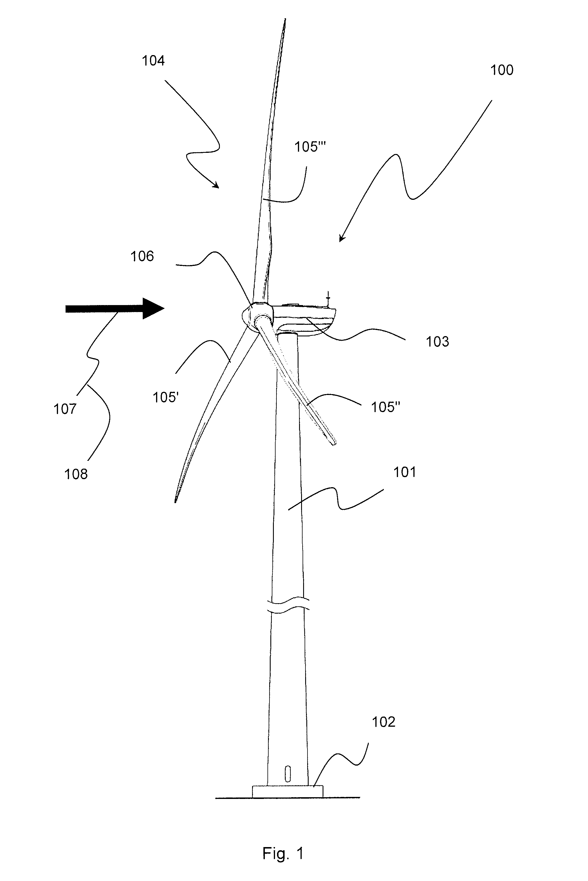
[0120]FIG. 1 shows a wind turbine 100 with a tower 101 raising from a foundation 102 and ended in a nacelle 103 with a wind turbine rotor 104 comprising, in this embodiment, three blades 105′, 105″, 105′″ assembled in a hub 106.

[0121]The nacelle 103 is rotably mounted on the tower 101 configured to face the wind 108 so that the wind 107 will rotate the turbine rotor 104 with a rotational speed depending on the wind speed 108.

[0122]FIG. 2 shows an embodiment of a drive train 200 placed in the nacelle 104 of the wind turbine 100. The drive train 200 connects the hub 106 via a shaft 201 to a gear box 202 that transforms the power to a primary generator shaft 204 that drives a primary generator 205. In this embodiment, the primary generator shaft 204 transfers power via a mechanical coupling 206 made as a toothed belt type arrangement to a secondary generator shaft 207 that drives a secondary generator 208.

[0123]The primary generator 205 is a Doubly Fed Induction Generator (DFIG) type g...


PUM

PropertyMeasurementUnit
maximum power outputaaaaaaaaaa

Abstract

This invention relates to a wind turbine of variable speed type including: a wind turbine tower; a nacelle on said wind turbine; a wind turbine rotor hub rotatably mounted at said nacelle, said wind turbine rotor hub having at least one wind turbine blade mounted thereon and a shaft coupled to said wind turbine rotor hub and to, optionally via a gear box, a primary generator which via power lines has a primary stator electrically connected to a grid connection and a primary rotor electrically connected to a back-to-back converter at a generator side converter end wherein the back-to-back converter at a grid side converter end is electrically connected to the grid connection. The wind turbine further includes a secondary generator coupled to the shaft via a mechanical coupling and electrically connected to the primary rotor of the primary generator and the generator side converter end of the back-to-back converter.

Description

BACKGROUND OF THE INVENTION[0001]1. Field of the Invention[0002]The present invention relates to a wind turbine with a primary and a secondary generator, a method of retrofitting a wind turbine having a primary generator to also have a secondary generator, and method of operating such wind turbines.[0003]2. Description of Related Art[0004]In particular, the present invention relates to a wind turbine of variable speed type comprising: a wind turbine tower; a nacelle provided on said wind turbine; a wind turbine rotor hub rotatably mounted at said nacelle, said wind turbine rotor hub having at least one wind turbine blade mounted thereon and a shaft coupled to said wind turbine rotor hub and to, optionally via a gear box, a primary generator which via power lines has a primary stator electrically connected to a grid connection and a primary rotor electrically connected to a back-to-back converter at a generator side converter end and wherein the back-to-back converter at a grid side ...

Claims


Application Information

Patent Timeline
Patent Type & Authority Patents(United States)
IPC IPC(8): H02P9/04H02P9/00F03D9/00
CPCH02P9/007F03D9/003F03D9/002Y02E10/725Y02E10/726Y10T29/49229F03D9/25F03D9/255F03D15/10Y02E10/72
Inventor ZHU, HONGDONG
Owner ENVISION ENERGY DENMARK
Features
  • R&D
  • Intellectual Property
  • Life Sciences
  • Materials
  • Tech Scout
  • Unparalleled Data Quality
  • Higher Quality Content
  • 60% Fewer Hallucinations
Learn More