Optical cable with improved strippability

a technology of optical cables and stripping, applied in the field of optical cables, can solve the problems of difficult pulling the cutter along the cable, difficult to separate the sheath from the tubular member, etc., and achieve the effect of reducing the thickness of the sheath to be cut, and facilitating the detachment of the cable sheath from the buffer tub

Active Publication Date: 2014-08-05
PRYSMIAN SPA
View PDF26 Cites 14 Cited by
  • Summary
  • Abstract
  • Description
  • Claims
  • Application Information

AI Technical Summary

Benefits of technology

[0021]In view of this problem it has been found that by providing a non-bonding separation element embedded in the inner portion of the sheath at the interface with the outer surface ...

Problems solved by technology

The engagement of the strength members with the tubular member (as well as with the sheath), while providing enhanced strength to the cable, causes the separation of the sheath from the tubular member to become relatively difficult.
However, it is difficult t...

Method used


Image

  • Optical cable with improved strippability
  • Optical cable with improved strippability
  • Optical cable with improved strippability

Examples


Embodiment Construction

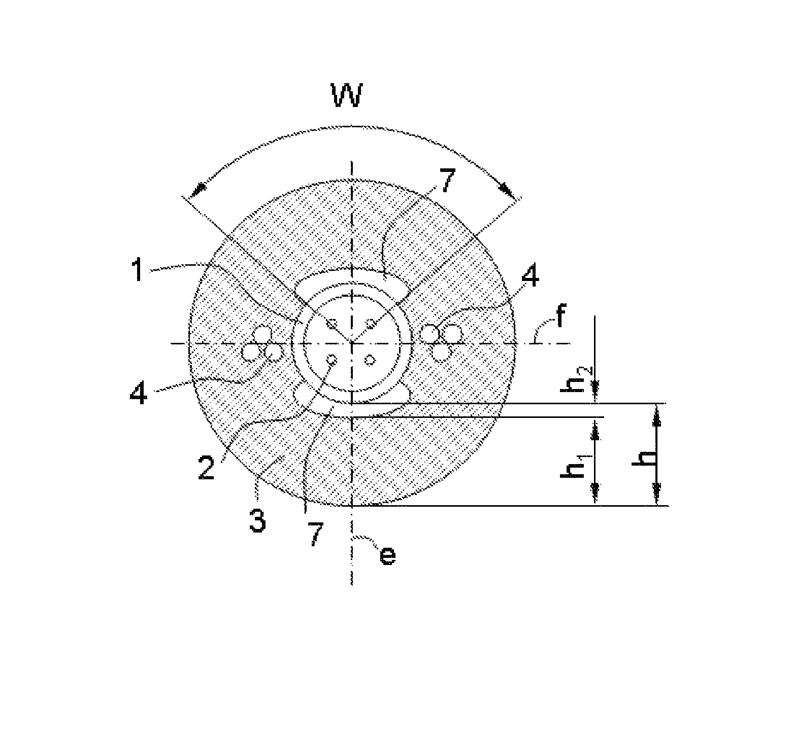
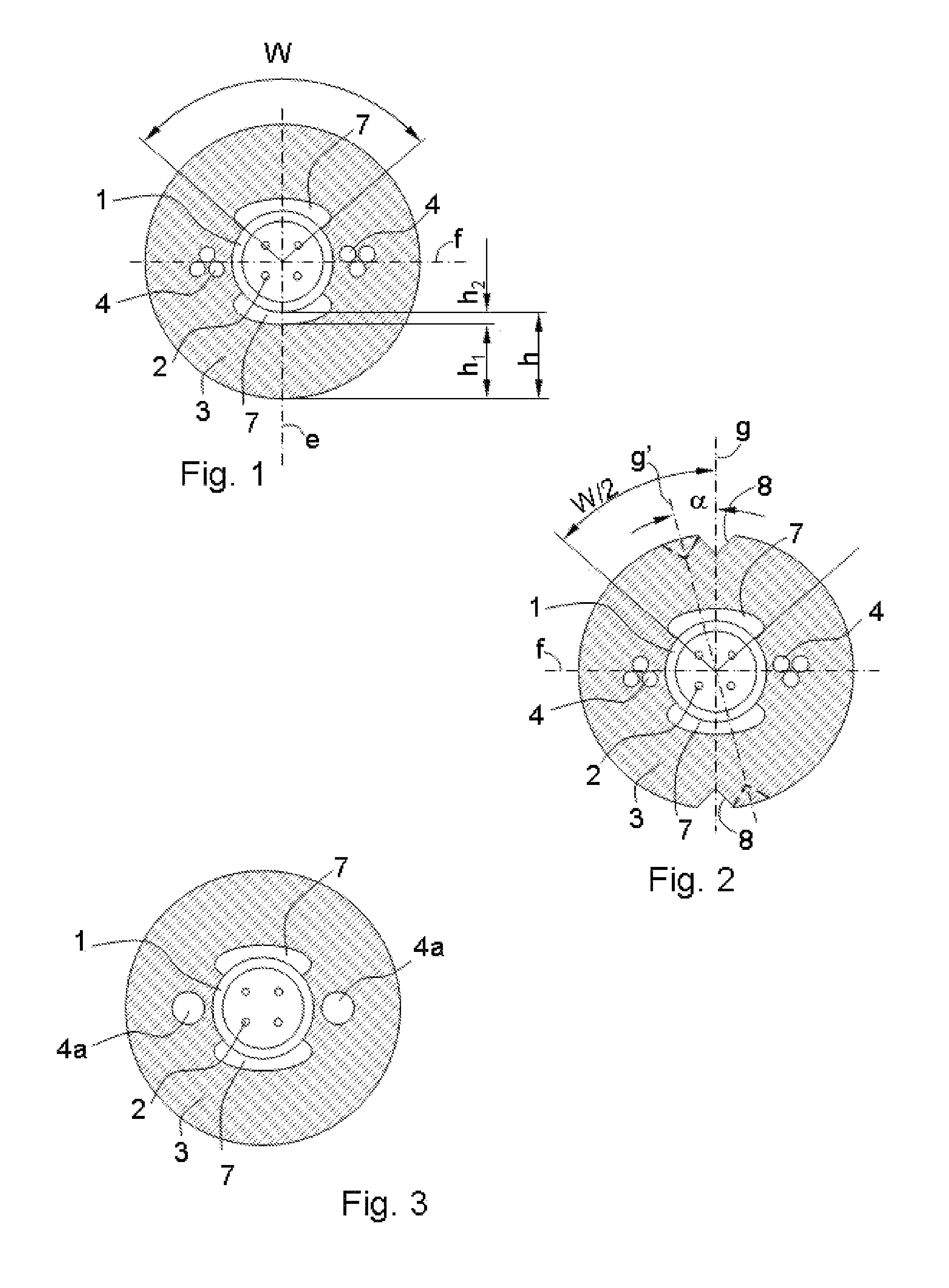
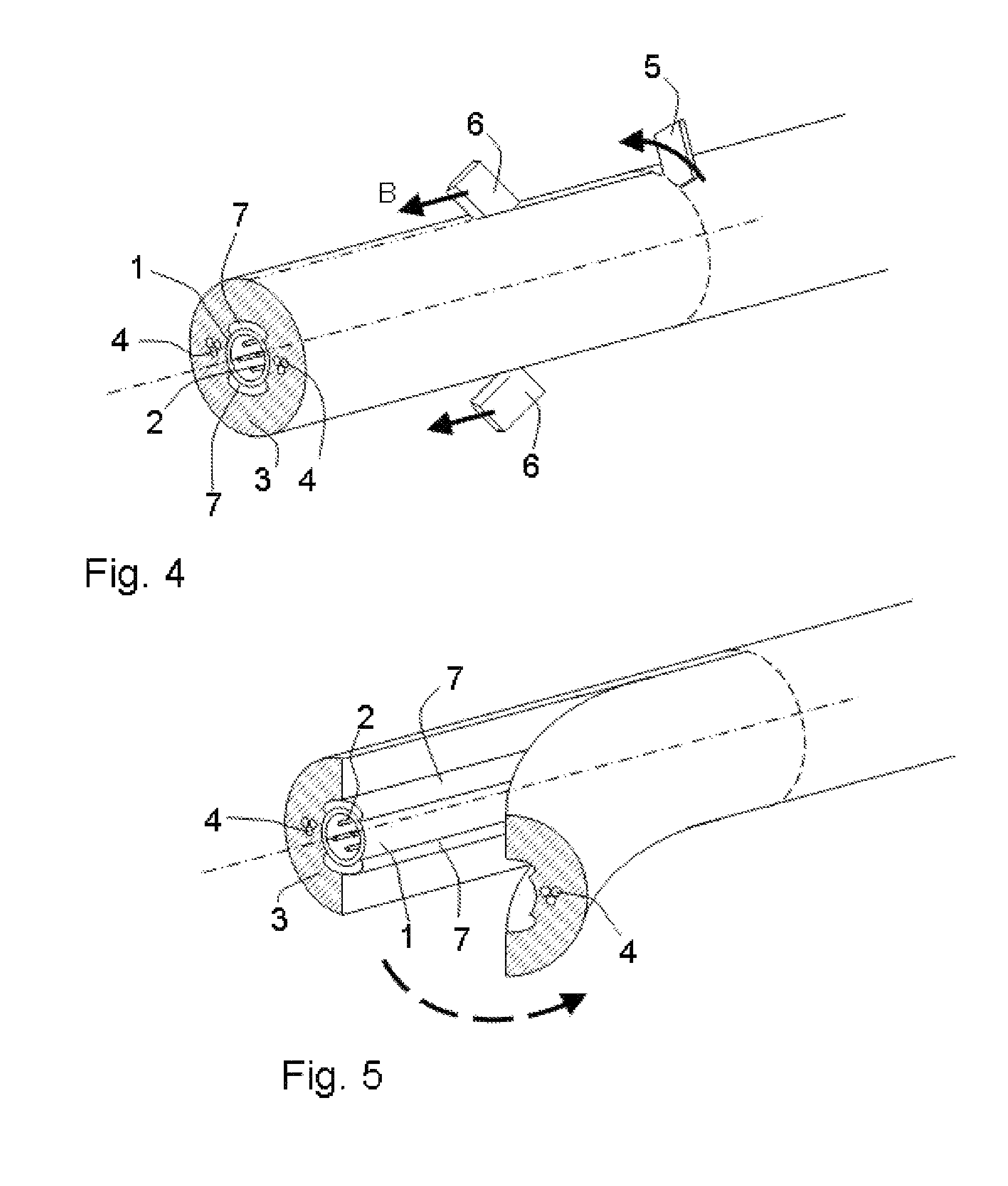
[0042]In the embodiment of FIG. 1 the cross-section of an optical cable is shown, which comprises a buffer tube 1, containing a number of optical fibers 2, surrounded by a sheath 3.

[0043]Typically the optical fibers 2 are loosely housed within the buffer tube 1, so that substantially no mechanical coupling is between fibers and buffer tube, thereby preventing a load applied to the buffer tube from being transmitted to the fibers.

[0044]Preferably, the buffer tube 1 is made of a thermoplastic polymer such as polybutylene terephthalate (PBT). The sheath 3 can be advantageously made of polyethylene, preferably high density polyethylene (HDPE).

[0045]Two diametrically opposed strength members 4 are embedded in the sheath 3.

[0046]In the embodiment of FIG. 1, each of strength members 4 can be made in the form of a strand of metallic wires (e.g. brass plated steel wires).

[0047]Alternatively, if a dielectric cable is desired, the strength members 4 can be dielectric, such as rods of glass or ...


PUM


Abstract

An optical cable includes a buffer tube housing at least one optical fiber, a sheath surrounding such buffer tube and at least one longitudinal strength member embedded in the sheath, in which at least one separation element is provided between a portion of the outer surface of the buffer tube and the inner surface of the sheath, laying in an axial plane not containing the at least one strength member.

Description

CROSS REFERENCE TO RELATED APPLICATION[0001]This application is a national phase application based on PCT / EP2009 / 053059, filed Mar. 16, 2009, the content of which is incorporated herein by reference.BACKGROUND OF THE INVENTION[0002]1. Field of the Invention[0003]The present invention relates to optical cables, and more specifically to optical cables comprising a buffer tube, housing the optical fibers, and a sheath around such buffer tube.[0004]A buffer tube loosely housing optical fibers is usually called “loose tube”.[0005]2. Description of the Related Art[0006]These cables are required to have a certain tensile strength both to withstand the stress during cable laying operations and to bear loads applied to the cable itself, for example in case of aerial installation.[0007]To this purpose the cable construction includes one or more strength members. Preferably diametrically opposed strength members are used.[0008]Typically, especially when a limited number of fibers are contempla...

Claims


Application Information

Patent Timeline
IPC IPC(8): G02B6/44
CPCG02B6/4495G02B6/4433G02B6/4431
Inventor DAVIES, MARTINFRAMPTON, SIMON JAMESPIKE, ROGERSUTEHALL, RALPH
Owner PRYSMIAN SPA
Why Eureka
Try Eureka