Skull clamp system with pressure limiting and alarm systems

a clamping system and alarm system technology, applied in the field of surgical and medical treatment practices, can solve the problems of unintentional bone fracture, potentially dangerous tactile feedback sensed by the surgeon, manual over-tightening of the clamping device to the skull of the patient, etc., to reduce the chance of a resulting infection, and minimize bleeding

Active Publication Date: 2014-08-12
SOLOMON CLIFFORD T +1
View PDF22 Cites 8 Cited by
  • Summary
  • Abstract
  • Description
  • Claims
  • Application Information

AI Technical Summary

Benefits of technology

[0010]The skull clamp system with pressure limiting and alarm systems comprises a skull support clamp having at least one but preferably multiple skull immobilizing pins projecting inwardly therefrom to adjustably engage and immobilize the skull of a patient. The skull support clamp includes at least one pin that is connected to a powered drive system but preferably will include four pins that are motor driven into a secure connection with the skull of a patient. The pins can be automatically and selectively driven into the outer portion of the bone using a powered drive system subject to the control of a preset back pressure limitation for the pins. Preferably the powered drive system is a motorized drive system. An electrical motor drive system is preferred; however, any other drive system such as pneumatic or hydraulic would could also effective serve to provide a powered or motorized drive system. The pins are designed to penetrate into the outer portion of the bone without rotating thus eliminating torsional forces being transmitted from the pin to the contact points on the bone. To avoid potentially destructive torque being applied to the pin-bone contact points, the pins are preferably driven into the outer layer of the bone by a linear directed force rather than a conventional rotationally directed force. At least the tips of the pins that will engage the scalp and skull of the patient can be treated with a suitable antibiotic to reduce the chance of a resulting infection at the contact site. The tips of the pins can also be treated with a blood-clotting agent to minimize bleeding at the pin-skull contact site.
[0011]The drive system provided for the pins can include a digital display to indicate to the surgeon, the amount of pressure being applied by the pin against the skull. This important information can also be transmitted by direct wired or by wireless means to a remote monitoring system for observation by another member of the surgical team assisting the surgeon. The drive system can also communicate an unsafe status of the pin contact with the patient's skull through an alarm, which can include both visual and audible alarms. This alarm system can alert the medical professional of any reduction of back pressure applied against the pins. Upon detection of an abnormal condition such as a decrease in back pressure of the bone against the pin, the pin drive system is capable of being automatically disabled. Early detection of a lessened back pressure on the pin and automatic stoppage of the pin drive system can protect against a pin penetration through the entire bone and potentially serious injury to the patient. Similarly, once the pins are securely in place if there is a loss or reduction of resistance or back pressure on the pin the sensors of the system can trigger an alarm to indicate a possible loosening or slippage of the skull clamp system that might permit the patient's head to move relative to the previously secured position. The skull clamp with its plurality of immobilizing pins is affixed to a framework that is in turn affixed to an operating table or other patient support structure such as a bed or examination table.

Problems solved by technology

One common example is during neurosurgery or other cranial surgery, during which the head of the patient must be completely immobilized due to the extremely delicate nature of the operation.
These early cranial immobilizing devices present various problems, with one obviously being the potential hazard of manually over-tightening the clamp on to the skull of the patient.
This conventional practice of the surgeon manually tightening the skull clamp on to the skull of a patient with the amount of pressure exerted by the clamp pins against the skull being controlled only by the tactile feedback sensed by the surgeon is potentially very dangerous.
In many instances the surgeon or other medical practitioner might unintentionally apply too much pressure to the skull as he or she manually tightens the threaded adjustment screw(s) to drive the pin(s) into the bone resulting in an unintentional fracture of the bone.
The difference between the tactile feedback from applying too little pressure or too much pressure in securing the pins to the skull can be exceedingly small in certain instances.
The amount of pressure applied in securing the pins into the outer layer of the skull is complicated by the wide diversity in bone thickness for different patients and even more so by the varied perception of pin pressure against the skull as sensed by individual surgeons during the exertion of manually operation of the clamping devices.
A misjudgment about the amount of pressure to apply in driving the pins into the outer layer of the bone can easily result in a skull fracture, which creates an unnecessary hazard for the patient.
It often occurs that the pins may seem initially to be correctly set and secured into the outer portion of the bone; however, during the course of the surgery some slippage of the pins from their initial position on the skull may occur.
When slippage of the connection of the pin to the skull does occur, the skull might move slightly with potentially disastrous results.

Method used


Image

  • Skull clamp system with pressure limiting and alarm systems
  • Skull clamp system with pressure limiting and alarm systems
  • Skull clamp system with pressure limiting and alarm systems

Examples


Embodiment Construction

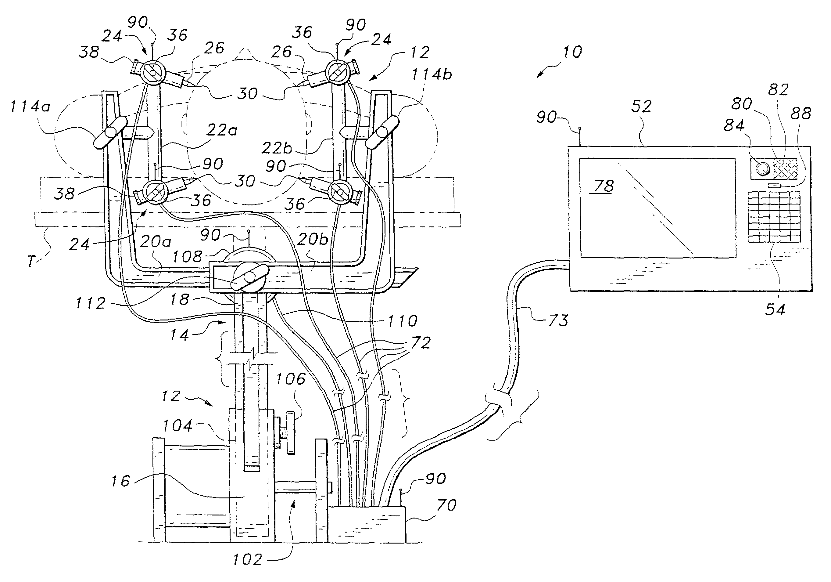
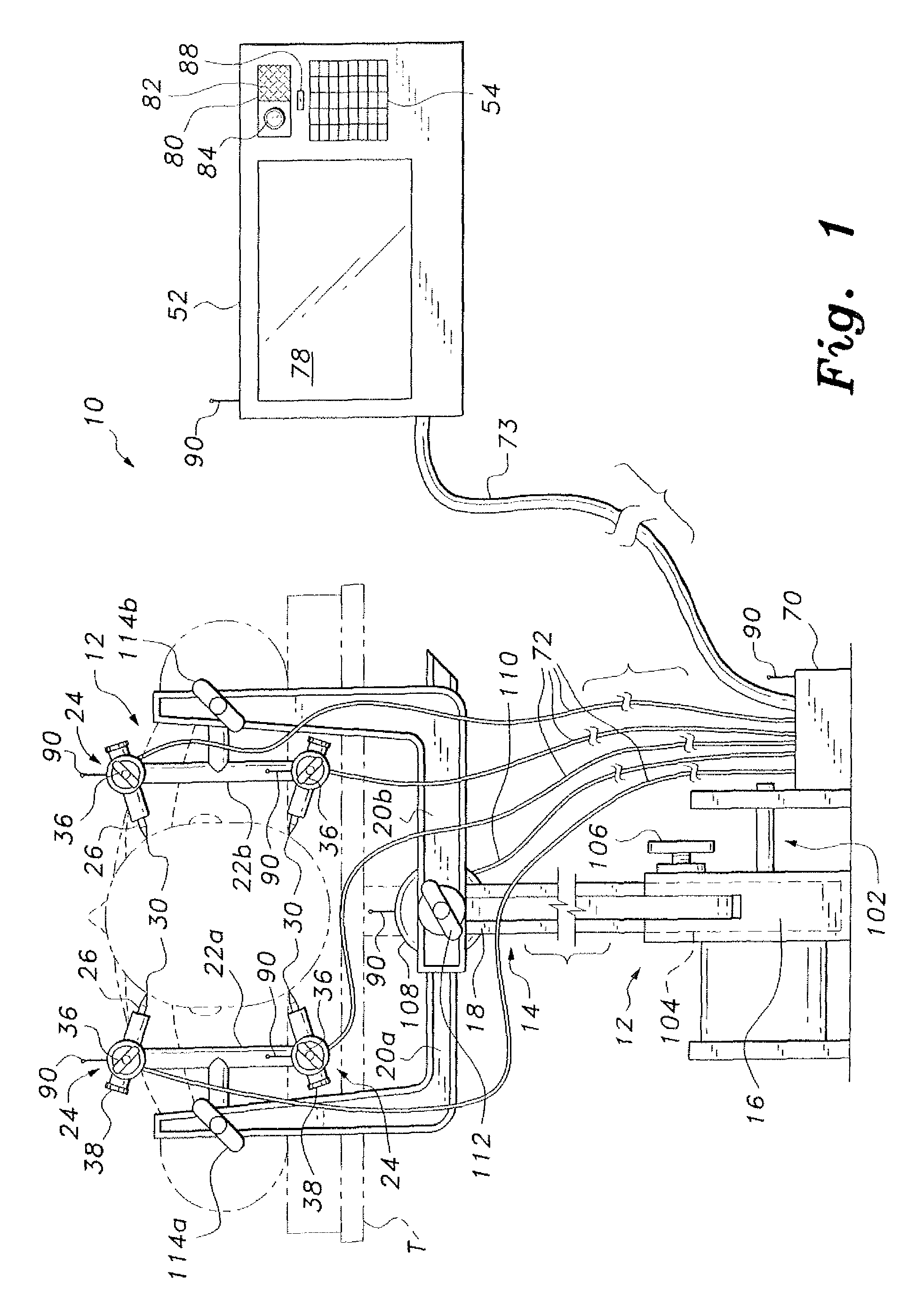
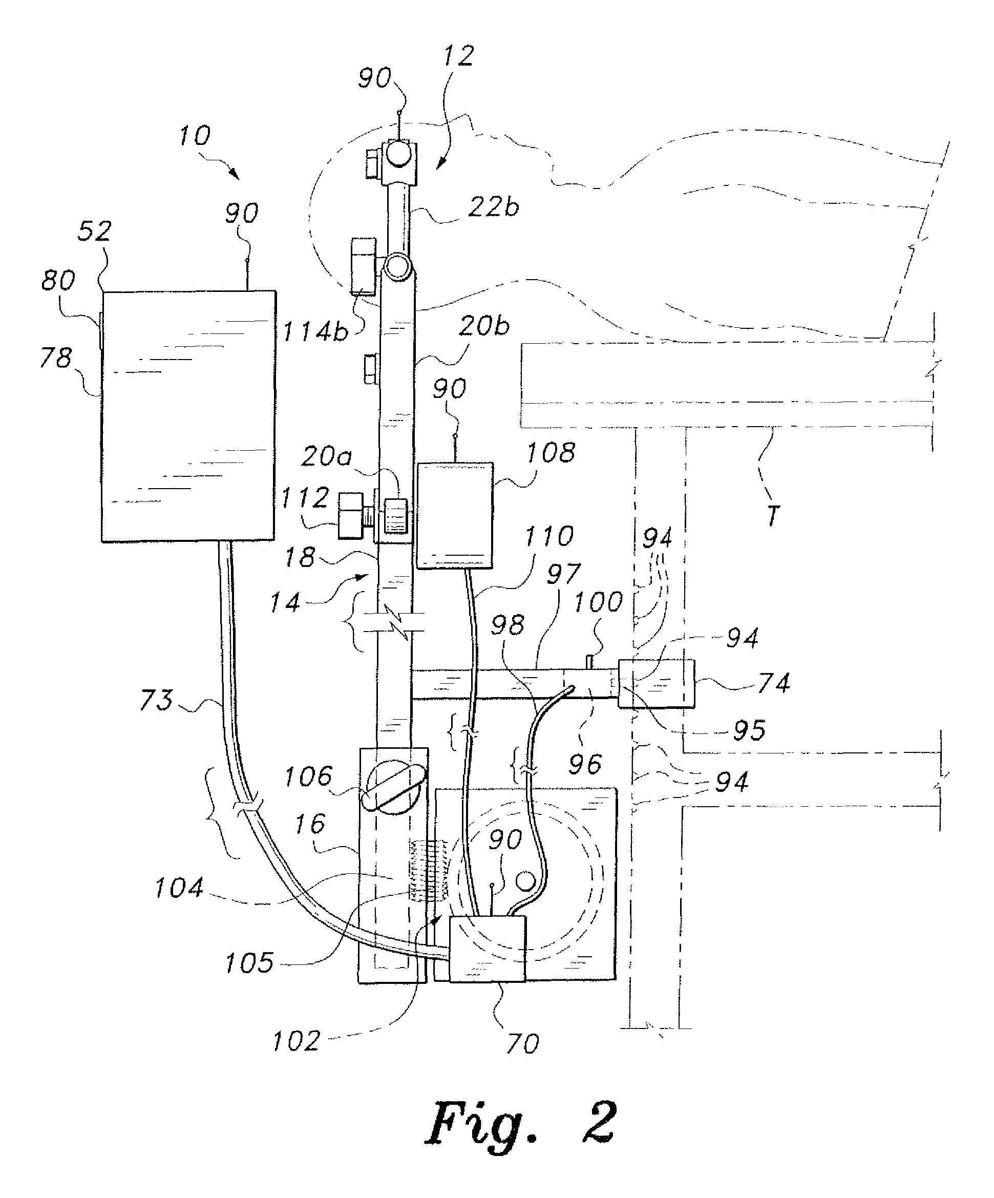
[0020]Referring to the accompanying figures, the following description of exemplary embodiments of the skull clamp system, generally shown at 10, is directed to a preferred embodiment having multiple skull immobilizing pins 26; however, the number of pins 26, which can be included in the system 10 and fully provide all of the power drive and safety systems is at least one.

[0021]The skull clamp system, as shown and described in FIGS. 1-6 and the accompanying description, having power driven skull immobilizing pins 26 and a sensor safety system 62 with pressure limiting and alarm systems, provides a structure capable of absolutely immobilizing the head of a patient for medical procedures. The skull clamp system 10 also includes means for limiting the pressure applied against the bone of the skull by each of the skull immobilizing pins 26, and means for alerting medical personnel of any slippage or movement of the pins 26 relative to the skull of a patient.

[0022]FIGS. 1 and 2 of the dr...


PUM


Abstract

The skull clamp system with pressure limiting and alarm systems includes at least one and preferably multiple inwardly power driven immobilizing pins adjustably engaging the skull of a patient. The pin power drive systems includes at least one sensor capable of sensing the degree of back pressure on the pin from contact of the pin against the bone of the patient, the sensor being capable of signaling the drive system to stop when the sensor detects a preselected degree of back pressure. The sensor is also capable of signaling an alarm to warn of any reduction of pressure applied to the pins that might result from pin slippage.

Description

CROSS-REFERENCE TO RELATED APPLICATION[0001]This application claims the benefit of U.S. Provisional Patent Application Ser. No. 61 / 497,800, filed Jun. 16, 2011.BACKGROUND OF THE INVENTION[0002]1. Field of the Invention[0003]The present invention relates to devices used in surgical and medical treatment practices, and particularly to a skull clamp device for immobilizing the skull. The device is particularly useful in immobilizing the skull during neurosurgical procedures while providing a sensor safety system for limiting the pressure exerted on the skull by the clamp and providing an alert to the medical team of any potentially hazardous application of clamp pressure or any loosening or slippage of the skull clamp device.[0004]2. Description of the Related Art[0005]There are many medical situations in which it is absolutely vital to immobilize the head of a patient receiving treatment. One common example is during neurosurgery or other cranial surgery, during which the head of the ...

Claims


Application Information

Patent Timeline
Patent Type & Authority Patents(United States)
IPC IPC(8): A61F5/37A61B17/00A61B17/62A61B19/00
CPCA61B17/62A61B17/6408A61B19/203A61B2017/00022A61B2017/00115A61B17/6433A61B90/14A61B17/6458
Inventor SOLOMON, CLIFFORD T.SOLOMON, THEODORE C.
Owner SOLOMON CLIFFORD T
Why Eureka
Try Eureka