Infundibular reducer devices

a technology of infundibular reducer and valve body, which is applied in the field of treatment of cardiac valve disease using prosthetic valves, can solve the problems of device shortening and lengthening, and achieve the effects of preventing thrombosis, reducing tissue ingrowth, and being easy to transplan

Active Publication Date: 2014-08-12
MEDTRONIC VASCULAR INC
View PDF20 Cites 240 Cited by
  • Summary
  • Abstract
  • Description
  • Claims
  • Application Information

AI Technical Summary

Benefits of technology

[0011]A benefit of some embodiments of the present invention is that the devices may be delivered through a catheter to a desired anatomic site and may expand without a need for a balloon to expand the devices. Delivery of devices without a balloon minimizes the bulkiness of the delivery system, which can allow for easier insertion and removal of the devices.
[0012]Another benefit of the present invention is that modularity of the devices allows different segments of the devices to expand and move independently. Thus, the devices are able to conform more closely to an irregular implanted site. Certain segments of the devices may rotate with respect to other segments, and the devices may shorten and lengthen. The devices are also able to move within the implanted site during the cardiac cycle, and still conform to the implanted site. As a result, the devices are more effective.
[0014]Yet another benefit of the devise of the present invention is that the devices are easily explantable. The stent portion may be peeled from the wall of the implanted site, collapsed, and the valve and stent may then be removed from the body.
[0015]A further benefit of the present invention is that drastic failure of the devices due to fracture of one wire or a few wires is eliminated. Since the stent portions of the devices are comprised of a plurality of wires that are independently connected in a plurality of locations to the fabric frame, fracture of one wire or a few wires does not cause the whole device to fail.
[0017]An additional benefit of some embodiments of the devices is that the devices may include materials that are antimicrobial, prevent thrombosis, and either increase or reduce tissue ingrowth. Such materials allow the devices to be better secured in a vessel, and decrease the chance of rejection of the devices.
[0018]Another benefit of the present invention is that the stent portion may later serve as a landing zone or site for implantation of a later-needed prosthetic valve. Another valve may be delivered percutaneously to the inner lumen of the device that is already implanted.

Problems solved by technology

Certain segments of the devices may rotate with respect to other segments, and the devices may shorten and lengthen.

Method used


Image

  • Infundibular reducer devices
  • Infundibular reducer devices
  • Infundibular reducer devices

Examples


Embodiment Construction

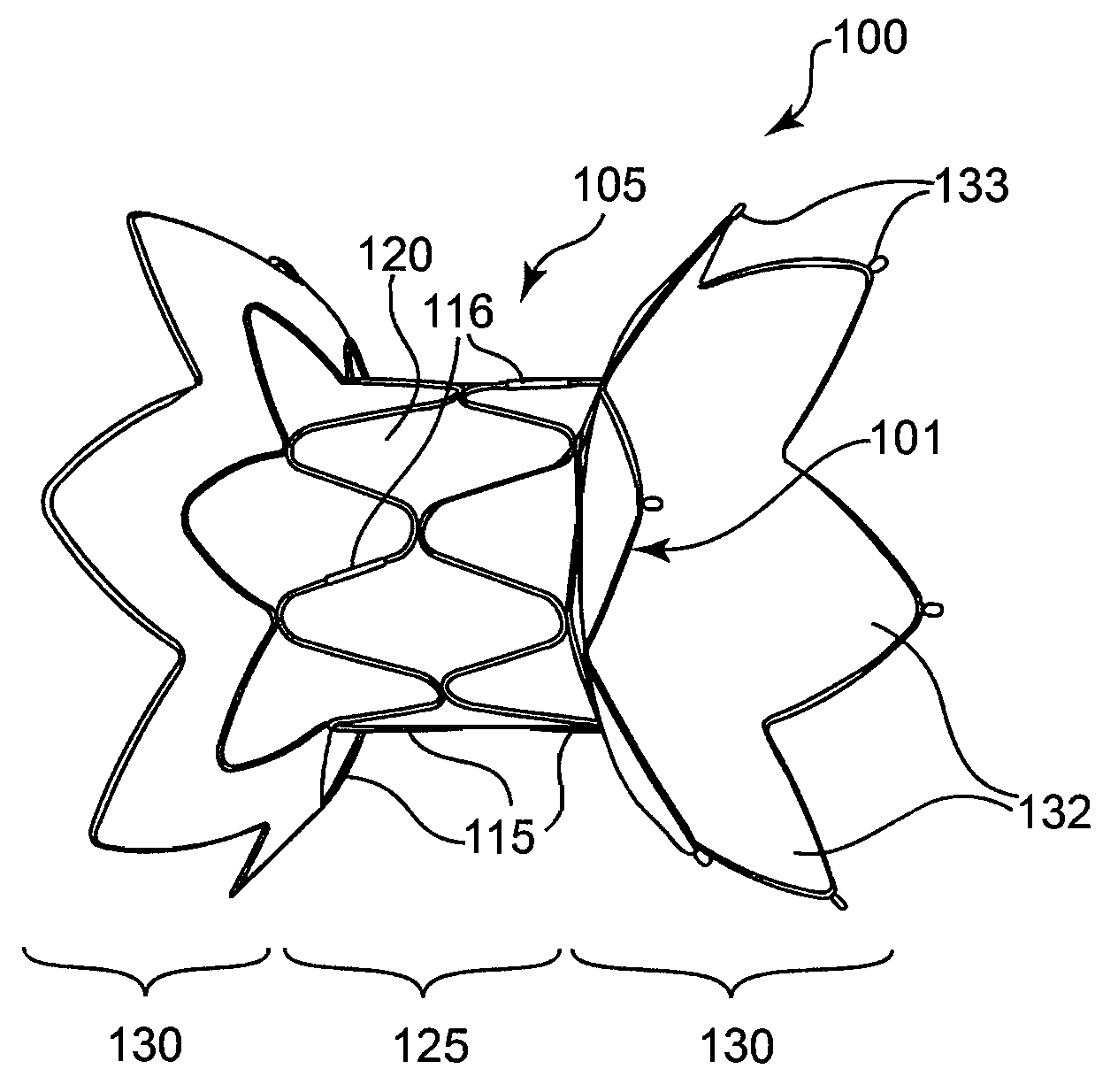
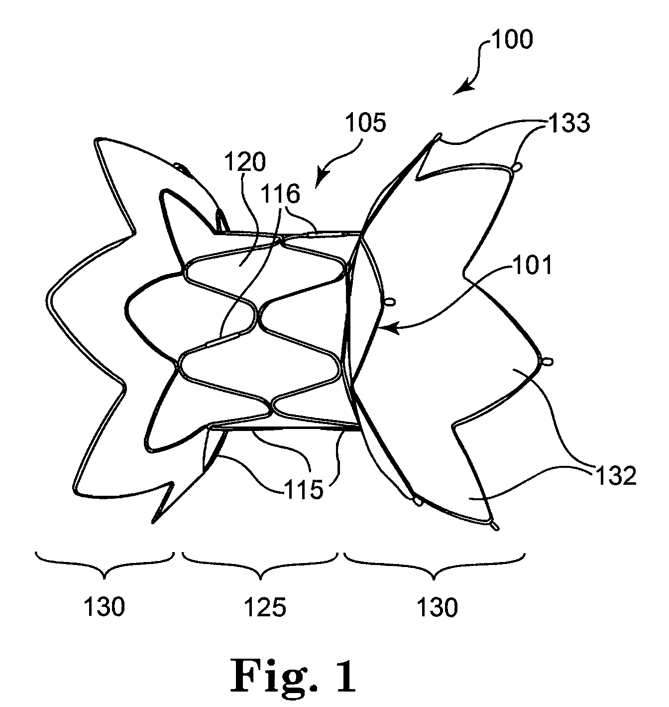
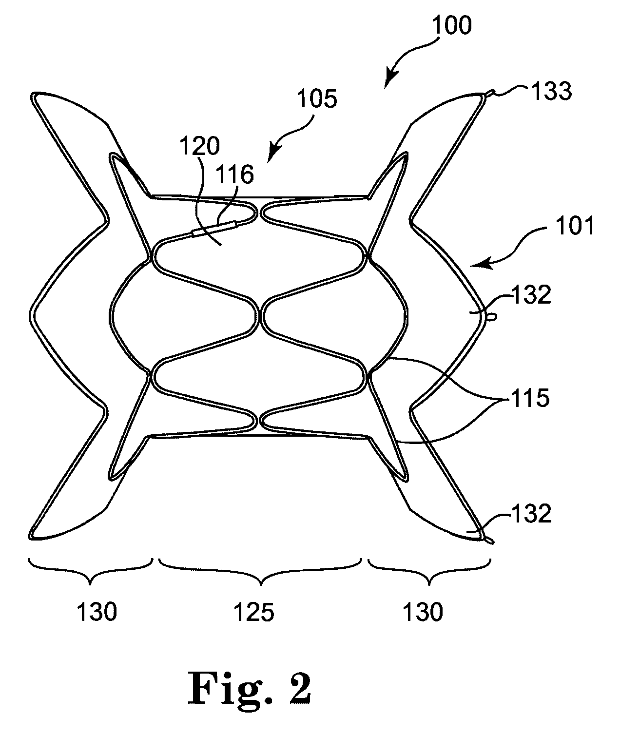
[0031]With reference to the accompanying figures, wherein like components are labeled with like numerals throughout the figures, illustrative infundibular reducer and related devices are disclosed, taught and suggested by the multiple embodiments. Although the devices are called “infundibular reducer” devices, the devices may be used in anatomic locations other than the infundibulum, such as the right ventricular outflow tract and other locations in or near the heart. In particular, the devices allow for prosthetic heart valves to be implanted in the right ventricular outflow tract or the infundibulum. The purpose of such devices is to allow replacement valves, such as pericardial heart valves, for example, having a smaller diameter than the diameter of the implanted site (e.g., the right ventricular outflow tract) to be implanted. However, the devices generally disclosed and shown may be used for other purposes as well.

[0032]The devices disclosed are beneficially configured such th...


PUM


Abstract

Described is a prosthetic valve assembly comprising: a radially self-expandable stent configured to expand to bear against a wall of a native body lumen; and an implantable prosthetic valve, having a diameter, the valve being mounted inside the stent; wherein the diameter of the stent is greater than the diameter of the prosthetic valve.

Description

CROSS-REFERENCE TO RELATED APPLICATION[0001]The present application claims priority to U.S. Provisional Application No. 61 / 031,266, filed Feb. 25, 2008, and titled “Infundibular Reducer and Related Devices,” the entire contents of which is incorporated herein by reference in its entirety.TECHNICAL FIELD[0002]This invention relates generally to the treatment of cardiac valve disease using prosthetic valves, and more particularly to replacement of malfunctioning pulmonary valves using infundibular reducer devices.BACKGROUND OF THE INVENTION[0003]Natural heart valves, such as aortic valves, mitral valves, pulmonary valves and tricuspid valves, often become damaged by disease in such a manner that they fail to maintain blood flow in a single direction. A malfunctioning heart valve may be stenotic (i.e., heart leaflets are closed down) or regurgitant (i.e., heart leaflets are wide open). Maintenance of blood flow in a single direction through the heart valve is important for proper flow,...

Claims


Application Information

Patent Timeline
Patent Type & Authority Patents(United States)
IPC IPC(8): A61F2/06
CPCA61F2230/0078A61F2250/0039A61F2230/008A61F2250/0048A61F2250/0023A61F2230/0054A61F2/2418A61F2/82A61F2/86A61M29/02
Inventor HOUSE, MORGANBONHOEFFER, PHILIPPRAFIEE, NASSERBUSOLD, RANY HUYNHDOUK, NAREAKMAS, JUAN-PABLOMACDONALD, STUARTFINNEY, MICHAEL
Owner MEDTRONIC VASCULAR INC
Why Eureka
Try Eureka