Dimmable screw-in compact fluorescent lamp having integral electronic ballast circuit

a compact fluorescent lamp and electronic ballast technology, applied in the field of electronic ballasts, can solve problems such as unfavorable flickering of the lamp tube, and achieve the effect of reducing the variation in the envelope of the sinusoidal lamp curren

Inactive Publication Date: 2014-08-12
LUTRON TECH CO LLC
View PDF27 Cites 7 Cited by
  • Summary
  • Abstract
  • Description
  • Claims
  • Application Information

AI Technical Summary

Benefits of technology

[0018]According to an embodiment of the present invention, a dimmable ballast circuit for a compact fluorescent lamp generates a lamp current through the lamp having a substantially constant envelope such that flicker in the lamp electromagnetic interference (EMI) noise on an AC voltage supply is minimized. The ballast circuit comprises a bus-voltage-generating circuit receiving an input from an AC voltage supply and producing a DC bus voltage characterized by a low-frequency voltage ripple, an inverter circuit receiving the DC bus voltage and generating a variable frequency square-wave output signal, and an output filter circuit receiving the square-wave output signal and generating a substantially sinusoidal lamp current through the lamp at the frequency. The inverter circuit has a control input provided with a drive control signal that determines the frequency of operation of the inverter circuit and thus the frequency of the square-wave output signal. The ballast circuit further comprises a control circuit producing the drive control signal provided at the control input of the inverter circuit to control the frequency of the square-wave output signal and thus the intensity level of the lamp. The control circuit receives a first signal related to a target intensity level of the lamp and a second signal related to the actual intensity level of the lamp. The control circuit comprises an error amplifier circuit for comparing the first and second signals to produce the drive control signal to cause the inverter circuit to operate at a frequency to illuminate the lamp at the target intensity level. The bus-voltage-generating circuit produces the DC bus voltage to define an envelope for the sinusoidal lamp current, and the error amplifier circuit operates in a frequency range such that the error amplifier circuit is responsive to the second signal at the frequency of the second signal thereby to adjust the frequency of operation of the inverter circuit to reduce variation in the envelope of the sinusoidal lamp current.
[0019]In addition, a dimmable compact fluorescent lamp adapted to receive a phase-control voltage from a dimmer switch is also described herein. The dimmable compact fluorescent lamp comprises a fluorescent lamp tube, and an electronic ballast circuit for receiving the phase-control voltage from the dimmer switch and illuminating the lamp tube in response to the phase-control voltage. The ballast circuit comprises an inverter circuit for generating a variable frequency square-wave output signal from a DC bus voltage and an output filter circuit receiving the square wave output signal and generating a substantially sinusoidal lamp current through the lamp tube at the frequency. The electronic ballast circuit further comprises a control circuit for producing a drive control signal that is provided to a control input of the inverter circuit to control the frequency of the square-wave output signal and thus the intensity level of the lamp tube. The control circuit receives a first signal related to a target intensity level of the lamp tube and a second signal related to the actual intensity level of the lamp tube. The control circuit comprises an error amplifier circuit for comparing the first and second signals to produce the drive control signal to cause the inverter circuit to operate at a frequency to illuminate the lamp tube at the target intensity level. The DC bus voltage defines an envelope for the sinusoidal lamp current, and the error amplifier circuit operates in a frequency range such that the error amplifier circuit is responsive to the second signal at the frequency of the second signal thereby to adjust the frequency of operation of the inverter circuit to reduce variation in the envelope of the sinusoidal lamp current.
[0020]According to another embodiment of the present invention, a lighting control system receiving power from an AC power source comprises a dimmable compact fluorescent lamp and a dimmer switch adapted to be coupled in series electrical connection between the AC power source and the dimmable compact fluorescent lamp. The dimmable compact fluorescent lamp includes a fluorescent lamp tube and an electronic ballast circuit for illuminating the lamp tube. The dimmer switch generates a phase-control voltage characterized by a duty cycle defining a target intensity level of the lamp tube of the dimmable compact fluorescent lamp. The electronic ballast circuit receives the phase-control voltage and illuminates the lamp tube in response to the phase-control voltage. The ballast circuit comprises an inverter circuit for generating a variable frequency square-wave output signal from a DC bus voltage and an output filter circuit receiving the square-wave output signal and providing a substantially sinusoidal lamp current through the lamp tube at the frequency. The electronic ballast circuit further comprises a control circuit for producing a drive control signal that is provided to a control input of the inverter circuit to control the frequency of the square-wave output signal and thus the intensity level of the lamp tube. The DC bus voltage defines an envelope for the sinusoidal lamp current, and the control circuit operates in a frequency range such that the control circuit adjusts the frequency of operation of the inverter circuit to reduce variation in the envelope of the sinusoidal lamp current.
[0021]According to another aspect of the present invention, a dimmable ballast circuit for a fluorescent lamp comprises: (1) an inverter circuit generating a variable frequency square-wave output signal, the inverter circuit having a control input provided with a drive control signal that determines the frequency of operation of the inverter circuit and thus the frequency of the square-wave output signal; (2) an output filter circuit receiving the square wave output signal and generating a substantially sinusoidal lamp current through the lamp at the frequency; (3) a non-linear amplifier circuit amplifying a lamp-current-feedback signal representative of the magnitude of the lamp current through the lamp; and (4) a control circuit producing the drive control signal provided at the control input of the inverter circuit to control the frequency of the square-wave output signal and thus the intensity level of the lamp. The control circuit receives a target-intensity signal related to a target intensity level of the lamp and compares the target-intensity signal and the lamp-current-feedback signal to produce the drive control signal. The control circuit operates at a bandwidth greater than approximately 10 kHz to cause the inverter circuit to operate at a frequency in order to illuminate the lamp at the target intensity level. For first values of the lamp current that are below a current threshold, the lamp-current-feedback signal is amplified by a first amount, and for second values of the lamp current that are above the current threshold, the lamp-current-feedback signal is amplified by a second, smaller amount, thereby increasing responsiveness of the control circuit to changes in lamp intensity levels at low lamp intensity levels.

Problems solved by technology

This fluctuation (or ripple) in the envelope IENV of the lamp current ILAMP can cause undesirable flicker in the lamp tube 22.

Method used


Image

  • Dimmable screw-in compact fluorescent lamp having integral electronic ballast circuit
  • Dimmable screw-in compact fluorescent lamp having integral electronic ballast circuit
  • Dimmable screw-in compact fluorescent lamp having integral electronic ballast circuit

Examples


Embodiment Construction

[0037]The foregoing summary, as well as the following detailed description of the preferred embodiments, is better understood when read in conjunction with the appended drawings. For the purposes of illustrating the invention, there is shown in the drawings an embodiment that is presently preferred, in which like numerals represent similar parts throughout the several views of the drawings, it being understood, however, that the invention is not limited to the specific methods and instrumentalities disclosed.

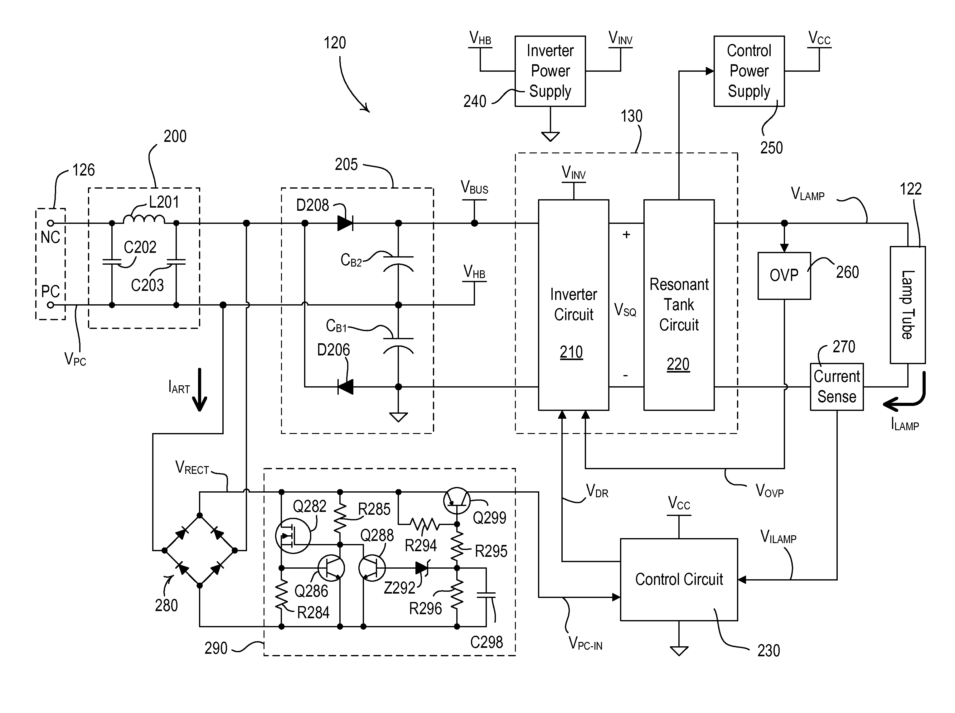
[0038]FIG. 4 is a side view of a dimmable screw-in compact fluorescent lamp 120 according to an embodiment of the present invention. The dimmable screw-in compact fluorescent lamp 120 comprises a light source, e.g., a fluorescent lamp tube 122, which may be formed in a spiral (as shown in FIG. 4), in two or more U-bends, or in any other suitable form. The lamp tube 122 may be filled with a fill-gas mixture having a fall-gas pressure of approximately 2 Torr and a fill-gas ratio o...


PUM


Abstract

A dimmable ballast circuit for a compact fluorescent lamp controls the intensity of a lamp tube in response to a phase-control voltage received from a dimmer switch. The ballast circuit generates a lamp current through the lamp tube having a substantially constant envelope such that flicker in the lamp tube and electromagnetic interference (EMI) noise on an AC voltage supply are minimized. The dimmable ballast circuit comprises a high speed control circuit characterized by a cutoff frequency much greater than a frequency of a voltage ripple on a bus voltage of the ballast circuit. The dimmable ballast circuit may also comprise a non-linear amplifier circuit amplifying a lamp-current-feedback signal representative of the magnitude of the lamp current through the lamp.

Description

CROSS REFERENCES TO RELATED APPLICATIONS[0001]This application is a non-provisional application of commonly-assigned U.S. Provisional Patent Application No. 61 / 484,481, filed May 10, 2011, entitled DIMMABLE SCREW-IN COMPACT FLUORESCENT LAMP HAVING INTEGRAL ELECTRONIC BALLAST CIRCUIT, the entire disclosure of which is hereby incorporated by reference.BACKGROUND OF THE INVENTION[0002]1. Field of the Invention[0003]The present invention relates to electronic ballasts for gas discharge lamps, such as fluorescent lamps, and particularly, a dimmable screw-in compact fluorescent lamp having an integral electronic ballast circuit.[0004]2. Description of the Related Art[0005]In order to save energy, high-efficiency lighting loads, such as, for example, compact fluorescent lamps (CFLs) and light-emitting diode (LED) light sources, are being used in place of or as replacements for conventional incandescent or halogen lamps. High-efficiency light sources typically consume less power and provide...

Claims


Application Information

Patent Timeline
Patent Type & Authority Patents(United States)
IPC IPC(8): H05B41/16H05B44/00
CPCH05B41/2828Y02B20/19H05B41/3925H05B41/16H05B33/0809Y02B20/00H05B45/39
Inventor NEWMAN, JR., ROBERT C.NACHTRIEB, ROBERT T.
Owner LUTRON TECH CO LLC
Why Eureka
Try Eureka